


Advance Automated Farm
The Advanced Automated Farm project leverages the Maixduino board for remote farm management, using AI voice commands and a mobile app. It simplifies farm tasks, improves efficiency, and boosts yields.
- Suitable forB.Tech IoT students
- Build time3-4 weeks
- LevelIntermediate
- Available atAjvika Labs, Kakinada
About this project
Here is my project Advanced Automated Farm, as in its name I automated the farm by using the Maixduino Development board got from the Digi-key. This project solves the major problems faced by the farmers when they are not available at the farm to maintain and other stuff to do so I came up with this idea.
The Advanced Automated Farm project is designed to support farmers managing large fields and multiple farms. This innovative system enables farmers to monitor and control their operations from anywhere in the world through a specially designed mobile app. By using AI voice commands, farmers can easily manage tasks in their regional languages, making it accessible for those who may not be familiar with technology.
This low-maintenance project is simple to install and use, ensuring that even illiterate farmers can benefit from its features. With real-time data and automation, farmers can optimize their resources, streamline their operations, and ultimately increase their yields. The Advanced Automated Farm project aims to transform the agricultural sector by empowering farmers to work more efficiently and effectively, ensuring they can thrive in a competitive market. This initiative envisions a future where technology helps every farmer reach their full potential. AI Projects and Tutorials is offering hands-on tutorials that demonstrate how to implement artificial intelligence on edge devices and embedded hardware.
1. Sipeed Maixduino AI & IoT kit
3. 5V Submersible Water Pumps
4. 2-Channel 5V relay modules (2)
5. Rain Sensor (HL - 83)
11. 3D Printed Parts
Watch the full demonstration by clicking on the YouTube video below :
FEATURES OF THE AAF:
There are 3 main features in this project:
Surveillance and Realtime monitoring
Surveillance and Realtime monitoring
1. Surveillance And Realtime Monitoring:
I came up with this feature cause at the Night times and when the farmer is far away from the farm there is no one to look after the farm so this Surveillance feature helps to monitor and control the camera to know what’s happening in the farm at any time and anywhere from the AAF app in their mobile.
I designed a simple and easy to use mobile app by using MIT APP INVENTOR to monitor and control all the activities in the farm from anywhere in the world through their mobile.
This app has so many features that helps the farmer to simplify their work. It can control the electrical devices like Motors, Lights, Fly traps, Rain Sensing mechanism in the farm and also has ability to turn on and off the voice commands and finally it can control the camera and shows the Realtime video footage in this app.
I included the voice control thanks to the MEMS microphone in the Maixduino board and has an ability to Recognise the voice commands and work with them. This feature helps the farmer when his mobile is not available or any other person want to look after the farm. I trained the voice commands in English as well as in my regional language this will helps the farmer who are poor in the English and easily control the farm.
Components Selected:
1. Sipeed Maixduino Devlopment Kit:
I choose this Maixduino board because it has powerful Ai K210 processor and a build in MEMS microphone so this board will be the perfect choice for this AAF project.
Even though there is an on board ESP32 in the Maixduino dev board, I choose to use an external one due to there is only one UART communication path in between the K210 and ESP32 so we need 3 UART communication paths to carry the Voice commands, App data and the camera data captured in k210 so it is better to use the external Esp32.
Here I am using the 2 channel relays (2) which are available to me it is better to use the 4-channel relay to fulfill this project. These relays act’s as the switches to control the devices in the farm.
I used the basic and most popular rain sensor HL-83 in this project to detect the rain and triggers an alarm in the farm.
I used this passive buzzer to generate alert signal when the rain I detected.
6. Submersible Water Pumps:
I am using the 5V small water pumps to represent the actual water pumps in the farm these are connected to the relays and can controlled by them.
I am using the 3mm 3.3v leds along with the 220ohm resistors to represent the actual lights and the Fly traps in the farm. These are also connected to the relay to be controlled by them.
This project runs on the battery power to simplify the reparability and also helpful when there are numerous Power-cuts. Here I am using 2 3.7V 18650 batteries to power the entire system.
Circuit Explanation:
I made this circuit diagram using the Fritzing and MS paint. This is the Overall circuit diagram of this project.
I connected the camera and Display to their respective slots. Then I connected the 3,4,5,6, pins of Maixduino to the relays. 6th pin of Maixduino is connected to the VCC of the rain sensor to power it on when required. The 7th pin of Maixduino is connected to the Buzzer Positive terminal. A0 analog pin of Maixduino is connected to the A0 pin of Rain sensor to read the data from it.
Then I established 3 UART connections in between the K210 and ESP32 to send and receive the APP data, Camera data and Voice command data. By establishing the 3 connections the data doesn’t interrupt with each other so this project will run smoothly.
Then I connected the devices like motors and lights to the relays. The entire project is powered by using the 2 18650 batteries and devices are powered using another external source.
I made this AAF app by using the MIT APP INVENTOR to control the entire project. Let us see how I made this app.
I added the firebase component to this app to be the database and storage in between the ESP32 and AAF app. I connected the Firebase to the app by using the Firebase token and Firebase URL. I also added the BASE64 component to this app to decode the base64 string of the captured image data.
These are the block code for the each and every Switch in the app, when a switch is ON in the app then it will write “1” in the Firebase otherwise ”0”. Then ESP32 takes this data from Firebase and sends the required signal to the K210.
This is the block code for the Firebase, whenever there is some change in data in Firebase then this program will make sure to update the switches position and everything in the app.
This is the layout for the screen-2 which displays the live video when camera switch is ON.
This is the Block code for the screen-2 and Decoding of the Base64 data into the image.
I used the Firebase as the Realtime database to store the device values and image data. This firebase is connected to the AAF app and also the ESP32 these two exchange the data by using this Firebase Realtime database feature.
After creating a Firebase basic account then I created a project with name AAF_APP.
After successfully creating the project then I added all the required variables to my project to hold the status of the devices. This will acts as mediator between the app and the ESP32.
VOICE MODEL TRAINING:
I trained the voice model to work with the voice commands, I trained the 13 commands in 2 languages ENGLISH & TELUGU to control the entire farm.
Here is the program that is used and it is from the GitHub repository from the SIPEED MAIXDUINO and i also given this program in my GitHub repository, it is pretty simple program whenever it we gave a voice command it will take the command and convert into MFCC codes.
#include \"Arduino.h\" #include \"Maix_Speech_Recognition.h\" #include \"voice_model.h\" SpeechRecognizer rec; void setup() { rec.begin(); Serial.begin(115200); Serial.println(\"start rec...\"); if( rec.record(0, 0) == 0) //keyword_num, model_num { rec.print_model(0, 0); } else Serial.println(\"rec failed\"); } void loop() { }
By using this program it gives the MFCC codes of your command along with a FRAME NUM, then we can use this code and frame number in our voice_model.h header file in our program
Then i pasted the frame number and also the MFCC code array.
NOTE/TIP: I faced the problem of only getting NOICE while training the commands then I changed the NOICE level in the header file \"Maix_Speech_Recognition.cpp\" from \"10000\" to \"50000\" this helps us in solving this problem
this is in line number:210
Similarly i changed in other place in the same file, it is for while running the program or working with sensors i got the same issue so it will be resolved by changing in here too.
This is in line number:295
By making this changes we can solve this problem.
After adding all the voice models then i use header file voice_model.h in my program. This is how i created my own voice model to this project.
I designed the case for this project by using the online platform ON SHAPE.
I designed this case into two parts where each part has mounts to hold the Components into it.
where the top part holds the Maixduino Dev board, display and other parts, the bottom half holds the relays and ESP32.
Finally I designed a simple case for my project with compact design within 120 X 100 X 50 mm.
Technologies used
Hardware components
- ESP32
- ESP8266
- Arduino
- DHT22
- Relay
- OLED
- NodeMCU
Software & tools
- Arduino IDE
- Blynk
- Firebase Console
- Node-RED
- MQTT Broker
Project demo video
What you get
- Working project / hardware kit, tested before delivery
- Complete source code with explanation
- Project demo and guidance for your viva
- Project report, PPT and IEEE paper support (on request)
Related IoT projects

DIY IoT Plant Watering System using Arduino
A remote plant-watering system that monitors soil moisture and lets you trigger a water pump from anywhere through the Blynk app, with LED-m...
View project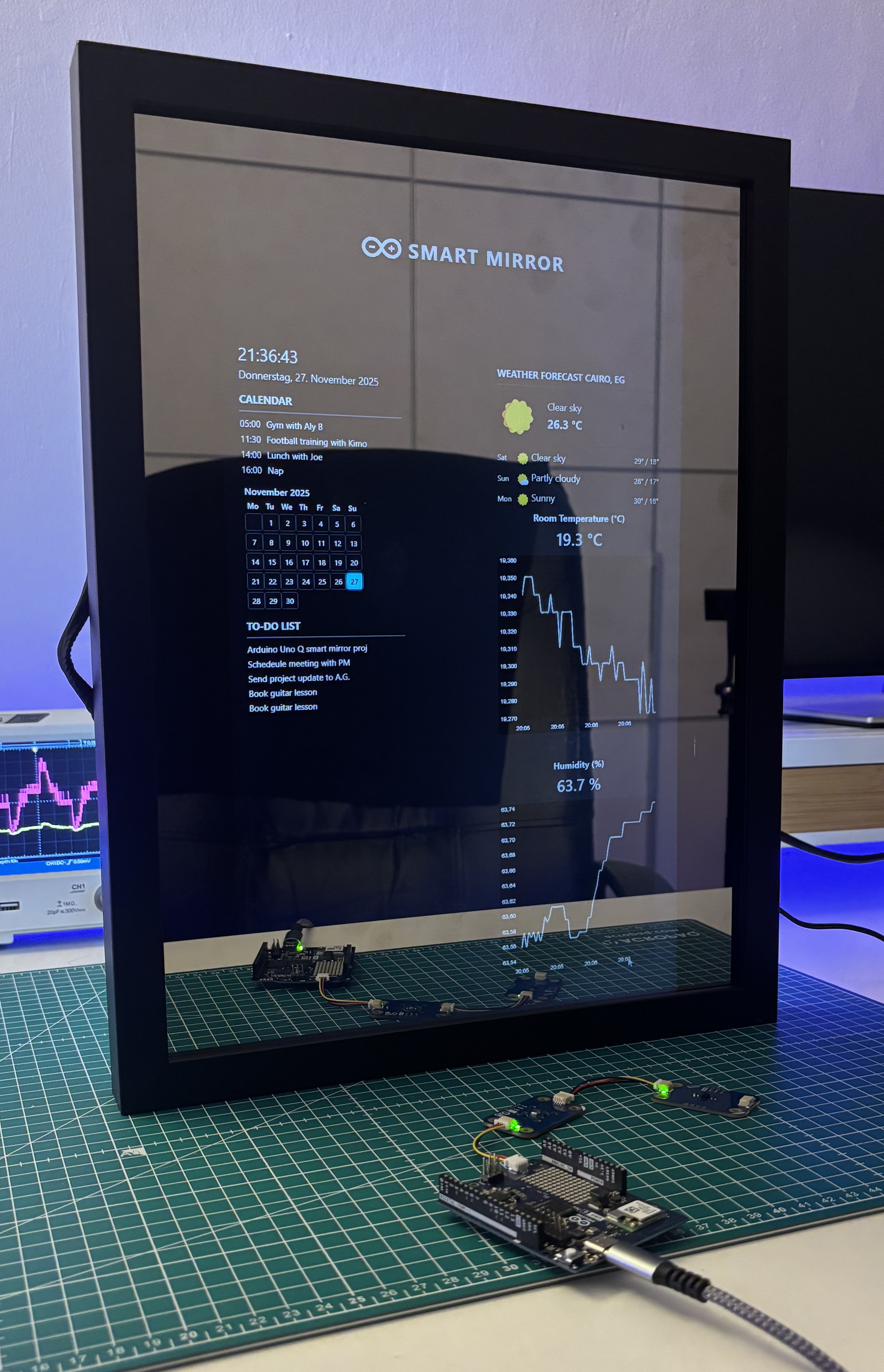
Build a smart mirror with an Arduino UNO Q
A wall-mounted smart mirror that shows the time, calendar, to-do list, room temperature/humidity and weather forecast behind a two-way glass...
View project
ESP32 Patient Health Monitor ECG SpO2 BPM Live Dashboard
Build a complete patient health monitoring system using ESP32 with AD8232 ECG sensor, MAX30102 pulse oximeter, BME280 and live web dashboard...
View project
IoT AC Energy Meter with PZEM-004T and ESP32 WebServer
Build an IoT-based AC energy meter using ESP32 and PZEM-004T to measure voltage, current, power, frequency and energy with live web dashboar...
View project