Wireless Stepper Motor Controller with ESP32 and TMC2240
Build a wireless stepper motor controller with ESP32, TMC2240 driver and web interface. Control stepper motors remotely through a web browser via WiFi with precision positioning and real-time feedback.
- Suitable forB.Tech Embedded students
- Build time3-4 weeks
- LevelBeginner
- Available atAjvika Labs, Kakinada
About this project
Wireless Stepper Motor Controller with ESP32 - Quick Overview
Build Time: 8-12 hours | Cost: $50-80 | Difficulty: Intermediate-Advanced
What You'll Learn: WiFi connectivity, SPI/I2C communication, USB-C Power Delivery, Microstepping control
Applications: Robotics automation, CNC machines, Home automation, Industrial prototyping
Wireless Stepper Motor Controller
Building the Stepper Motor Controller
Programming the ESP32
Firmware Upload and Web UI Testing
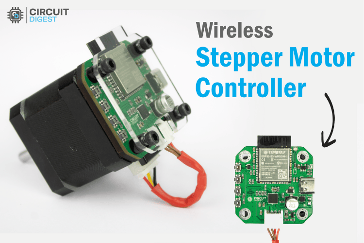
In this guide, we introduce a custom-built Wireless Stepper Motor Controller with ESP32, a simple yet powerful way to add Wi-Fi stepper motor control to any project. This wireless stepper motor driver integrates robust control with modern connectivity, making it perfect for applications in automation, robotics, and industrial prototyping. With this wireless stepper driver design, you can control the motor directly through a local web interface, no extra software or complex setup required.
This project was made possible thanks to our sponsors, DigiKey. All the components used in this project were built using parts from DigiKey. You can check out our Project Files with PCB Gerber and BOM to build this wireless stepper motor controller project on your own.
Wireless Stepper Motor Controller - Explained
The Wireless Stepper Motor Controller with ESP32 is a smart motor control system that combines precision stepper motor control with wireless connectivity and intelligent power management.
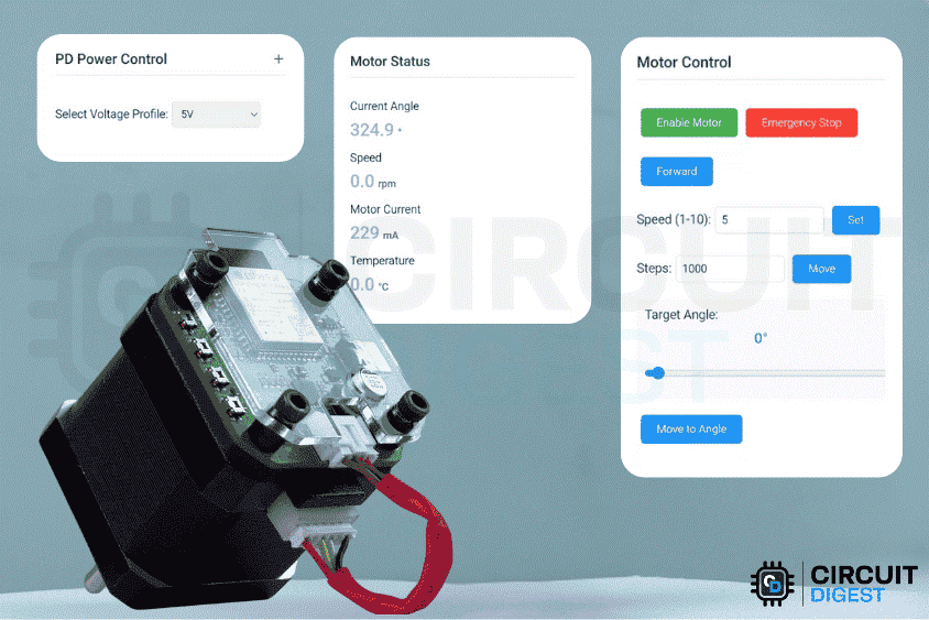
Wireless Stepper Motor Control: Operate your motor remotely via a simple web interface on any browser or smartphone.
Precision and Accuracy: Achieve high-precision positioning with up to 1/256 microstepping and real-time encoder feedback from the AS5600 sensor.
Smart Power Management: Automatically negotiate optimal power levels from USB-C Power Delivery (PD) sources, from 5V to 20V.
Real-time Monitoring: Monitor critical data, including motor temperature, current draw, and exact position, all updated live on the web dashboard.
Intuitive Visual Feedback: Use colour-coded RGB LED indicators to instantly see the system's power status and motor activity.
Key Features of our Wireless Stepper Driver
Web-Based Control: Simple HTTP commands control all motor functions - no special software needed
Precision Movement: up to 1/256 microstepping with closed-loop positioning using AS5600 magnetic encoder
Smart Power Management: Automatically selects 5V, 9V, 12V, or 15V from USB-PD sources
Visual Feedback : RGB LEDs show power level (colour-coded) and motor activity (blinking patterns)
Real-Time Monitoring : Live status updates including temperature, current draw, and position
Non-Blocking Operation: The Web server stays responsive while the motor runs smoothly
Components Required for the Wireless Stepper Motor Controller Project
Wi-Fi and Bluetooth 5.0-enabled microcontroller module with dual-core Xtensa LX7 processor, 512KB SRAM, and 8MB flash memory.
High-precision stepper motor driver with SPI control, supporting up to 2A current and ultra-quiet operation.
Contactless magnetic rotary position sensor with 12-bit resolution for accurate angle measurement.
Low-dropout (LDO) linear regulator supporting 2.7V–40V input and up to 200mA output current.
USB Type-C controller with Power Delivery (PD) support for voltage negotiation and data role switching.
Voltage supervisor IC with push-pull output for reliable system reset management.
P-channel MOSFET (30V, 4A) for low-side switching applications.
Tactile push-button switches (6x6mm, 160gf actuation force) for user input.
40V transient voltage suppression (TVS) diode for circuit protection from voltage spikes.
TVS diode array designed for USB and ESD protection.
Red surface-mount LED (0603 package) for status indication.
RGB LED (common cathode, 1615 package) for multi-colour visual feedback.
Other Passive Components
Includes capacitors, resistors, and necessary discretes.
Miscellaneous connectors as required.
Main printed circuit board for the system.
Enclosures and mechanical supports.
Other Tools & Consumables
Assembly and testing materials.
Wireless Stepper Motor Controller with ESP32 Wiring Diagram
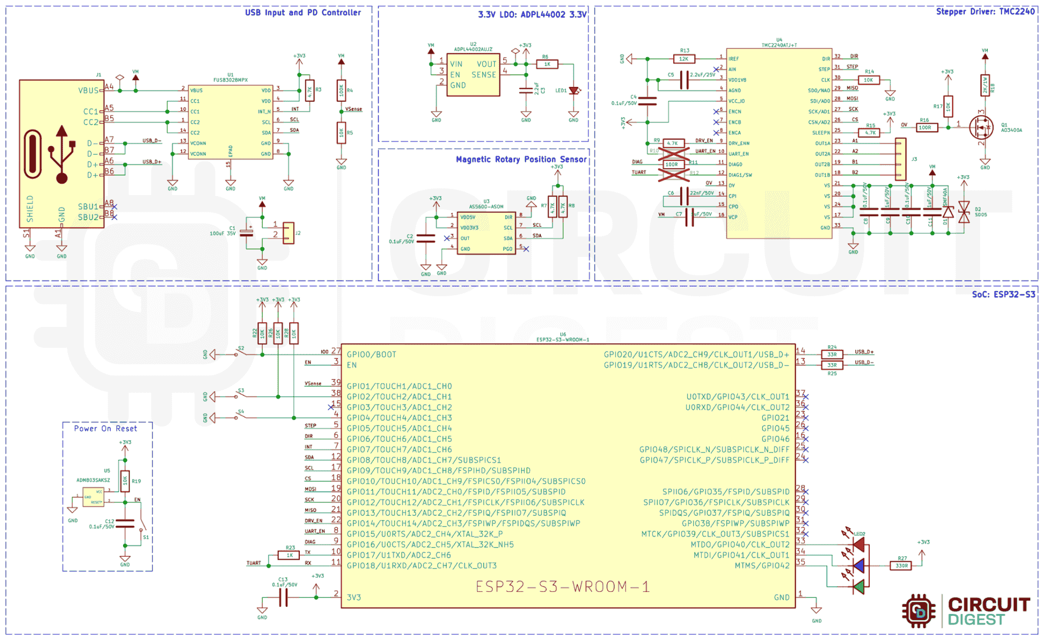
The complete circuit diagram for the Wireless Stepper Motor Driver is shown below. This comprehensive wireless stepper motor controller with ESP32 wiring diagram demonstrates how to control a stepper motor with ESP32 effectively. It can also be downloaded in PDF format from the GitHub repo linked at the end.
The schematic is fully customizable. You can tweak any part of the design to suit your specific needs.
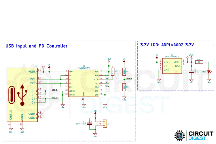
First, the power section, which combines a USB Power Delivery (PD) controller and a Low Dropout (LDO) regulator to manage voltage input and provide a stable 3.3V output. The USB PD controller used is the FUSB302BMPX, which negotiates power profiles through the USB-C connector. It connects to the CC1 and CC2 lines via 5.1kΩ pull-down resistors to detect cable orientation and voltage profiles. Once a power contract is negotiated, the VBUS line delivers the required voltage (e.g., 9V or 12V), which is then passed to the LDO regulator.
The LDO used is the ADP4140002, which steps down the negotiated voltage to a clean 3.3V. This 3.3V is used to power the ESP32-S3 microcontroller, the stepper motor driver’s logic section, the magnetic position sensor, and the indicator LEDs.
The LDO includes input and output capacitors for voltage stability and noise filtering, while the PD controller communicates with the ESP32-S3 via I²C and notifies it of any power events using an interrupt pin.
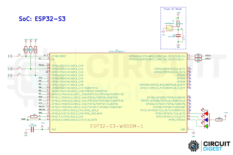
The core of the system is the ESP32-S3-WROOM-1 module, which provides Wi-Fi and Bluetooth connectivity along with multiple GPIOs for control and communication. This setup demonstrates exactly how to control a stepper motor with ESP32 efficiently. Its GPIO0 and EN pins are connected to push buttons for boot mode and reset functionality. It communicates via USB using its native D+ and D– pins, which are routed through 33Ω resistors. Previously, we have built many projects using ESP32 board; you can also check them out if interested.
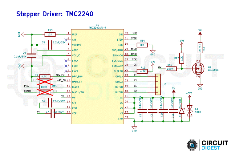
The I²C bus on GPIO9 (SCL) and GPIO8 (SDA) connects to the USB PD controller and the magnetic position sensor, allowing two-way communication for power and position monitoring. The ESP32 also interfaces with the TMC2240 stepper driver through both SPI and dedicated control pins. It uses GPIO10–13 for SPI communication and GPIO5 and GPIO6 for STEP and DIR signals.
In addition, three LEDs are connected to GPIO40, GPIO41, and GPIO42 via 330Ω resistors, which serve as status indicators.
The TMC2240 stepper motor driver handles the precise control of a stepper motor. It receives its motor power input (VM) from an external power source and logic power from the 3.3V LDO. The motor is controlled using STEP and DIR signals from the ESP32, while the SPI bus is used to configure internal settings and read diagnostics. The driver also includes enable and diagnostic pins for fine control and feedback. Protection is implemented using a TVS diode across the VM line to handle voltage spikes and sense resistors for monitoring motor current. The driver’s output pins are connected directly to the motor coils, enabling smooth microstepping operation. For those using A4988 drivers, our A4988 Arduino interface tutorial will guide you step by step.
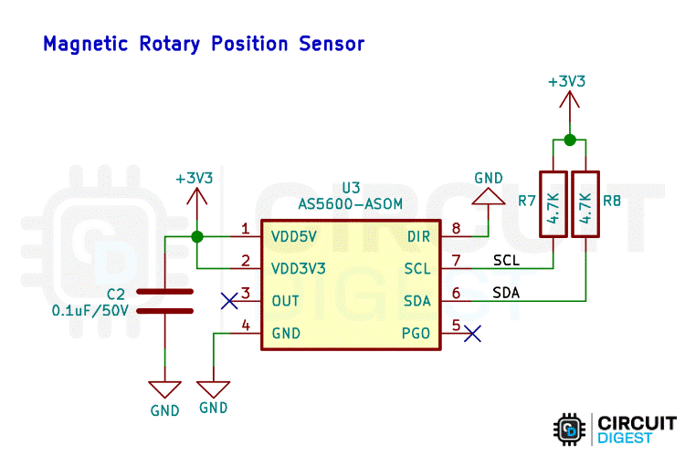
A magnetic rotary position sensor, based on the AS5600, is included for detecting the angular position of a rotating shaft. This sensor communicates over I²C, sharing the same bus as the PD controller. It is powered by the 3.3V rail and includes a decoupling capacitor for noise filtering. The sensor provides precise angle data to the ESP32, enabling closed-loop motor control or position tracking applications.
With this, the Schematic part gets covered. Next comes the PCB Part.
By integrating a versatile ESP32 microcontroller with the high-performance TMC2240 driver and an AS5600 encoder, this ESP32 stepper motor control wifi system provides unmatched precision and real-time feedback.
Custom PCB Design for Wireless Stepper Driver
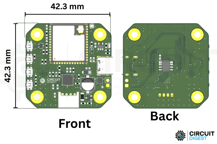
For this project, we decided to create a custom PCB. This ensures that the final product is as compact as possible and easy to assemble and use. The PCB was designed using KiCad, and all the design files are available for download from the GitHub repository linked below this article. The PCB dimensions are approximately 42.3 mm x 42.3 mm, which is exactly the general size of stepper motors like the NEMA 17. So, it easily mounts behind the motor.
Once the PCB design was complete and fully verified, we sent the respective Gerber files to a PCB fabrication service for manufacturing. Below, you can see the raw fabricated PCB.
Assembling Guide: Building the Stepper Motor Controller
The first step in assembling the PCB was to sort all the required components as listed in the BOM (Bill of Materials). After sorting, we placed the components on the PCB and soldered them one by one.
To simplify this process, you can use an SMD stencil to apply solder paste and then place the components before reflowing the PCB using either an SMD rework station or a reflow oven. However, you are not limited to these methods; manual soldering works just as well for small batches.
Above is the image of a fully assembled Wireless Stepper Motor Controller PCB.
Laser Cut Enclosure for Stepper Driver
To make the enclosure simple and quick, we chose laser cutting. There are two primary parts we need, along with some washers. At the bottom, we actually need a spacer to compensate for the magnetic encoder IC’s height. On the top, we need to cover the PCB to avoid external damage.
Above, you can see the image of the cutouts.
Below, you can see the components required for assembling the Wireless Stepper Motor Driver.
The assembly is very simple. The only part that requires extra attention is the placement of the magnet on the shaft. This is important, as it is responsible for sensing the shaft's position.
I broke a normal 3mm diameter magnet in half and placed one half as shown in the image below. I used Feviquick to stick the magnet.
Next comes the enclosure. It is assembled as shown in the following image.
After full assembly, the final project looks like the image below. You can see the compactness of this project.
The reason for not including any side enclosures is to provide ventilation for the driver IC, making it a perfect companion for fast prototyping.
This DIY wireless stepper motor controller project offers a powerful and compact solution for robotics projects and home automation projects. By integrating a versatile ESP32 microcontroller with the high-performance TMC2240 driver and an AS5600 encoder, this system provides unmatched precision and real-time feedback. Its web-based control and smart power management make it an ideal tool for rapid prototyping, robotics, and industrial applications. You can download all the code and design files from the GitHub repository linked below to build your own.
Technical Summary and GitHub Repository
A quick technical summary that outlines the main idea, principle of operations, and main properties of the project. In addition, the GitHub Repository includes the source code, design files, and documentation for ease of use. This summary provides the reader with a quick overview of the project and a sufficient method to replicate it with open-source materials.
Programming the ESP32: Arduino Code Overview
The core of this wireless stepper motor controller project is its versatile Arduino code, which seamlessly integrates several advanced technologies. The firmware demonstrates exactly how to control a stepper motor with ESP32 and is designed to combine:
TMC2240 Stepper Driver: For ultra-quiet and precise stepper motor control.
Technologies used
Hardware components
- ESP32
- Arduino
- Motor
- Stepper
- LED
- Button
- Sensor
- Module
- Board
- PCB
Software & tools
- KiCad
Project demo video
What you get
- Working project / hardware kit, tested before delivery
- Complete source code with explanation
- Project demo and guidance for your viva
- Project report, PPT and IEEE paper support (on request)
Related Embedded projects

ESP32 Fingerprint Attendance System with Live Web Dashboard
Build a biometric attendance system using ESP32 with AS608 fingerprint sensor that logs attendance with timestamp to web dashboard and Googl...
View project
Mars Rover Robot Replica using ESP32 CAM and Arduino
Build a Mars Rover robot replica using ESP32-CAM and Arduino with a rocker-bogie suspension system, live video streaming, and smartphone app...
View project
ESP32 CAN Bus Tutorial Interfacing MCP2515 with ESP32
Learn CAN bus communication with ESP32 and MCP2515 CAN controller to send and receive data in automotive and industrial applications.
View project
ESP32 MP3 Music Player with SD Card and I2S Amplifier
Build a standalone ESP32 MP3 music player that reads audio from SD card and outputs high-quality audio via I2S DAC amplifier with web contro...
View project