
Understanding Thermal Printers and How to Use it with ESP32
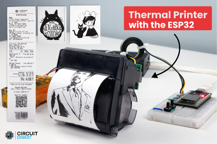
Learn how to interface ESP32 thermal printer with complete tutorial. Includes PNP-500 wiring, Arduino code, circuit diagrams, and projects for receipt printing, barcodes, and QR codes. Perfect for microcontroller projects and IoT applications.
- Suitable forB.Tech Embedded students
- Build time3-4 weeks
- LevelBeginner
- Available atAjvika Labs, Kakinada
About this project
Thermal printers are widely used in point-of-sale systems, medical equipment, and embedded applications because they require no ink, operate silently, and offer fast printing speeds. By interfacing a thermal printer with ESP32, you can create powerful IoT printing solutions for smart home automation, industrial monitoring, or custom receipt printing systems. Previously, we have also covered how to use a thermal printer with Arduino Uno and how to use a thermal printer with Raspberry Pi. You can check them out if you are interested.
ESP32 Thermal Printer Interface - Quick Overview
Build Time: 3-5 hours | Cost: $30-50 | Difficulty: Beginner-Intermediate
What You'll Learn: UART communication, ESC/POS commands, Bitmap image processing, QR code and barcode printing
Applications: Receipt printing, IoT monitoring, Smart home automation, Barcode labelling
Thermal Printer Types Comparison
How to Program a Thermal Printer?
└ Thermal Printer Commands
Thermal Printer ESP32 Circuit Diagram
Project Summary and GitHub Link
ESP32 Code for Thermal Printer Interface
Understanding Thermal Printer Basics
Thermal printing is a non-impact printing method that uses heat to produce images or text on specially coated heat-sensitive paper, known as thermal paper. It prints by passing the thermal paper over a print head that is specifically designed for this purpose, which has heating elements arranged in a fine line or dot matrix. When specific areas of the thermal paper are heated, a chemical reaction causes those spots to darken, creating the required print.
The thermal paper for this printer starts from 57mm, 76mm, 80mm, up to 110mm in width, and ranges from 15m to 70m in length. So, depending on the machine’s capability, specific widths and lengths of paper are used.
Thermal Printer Types Comparison
Key Features/Use Cases
Typical Applications
Heat-sensitive paper
No ink/toner, simple, low maintenance, silent, prints may fade over time
Receipts, shipping labels, barcode labels, tickets
Plain paper + ink ribbon
More durable prints, uses ink ribbon, can print in color, longer-lasting prints
Product labels, ID tags, asset tracking, wristbands, archival labels
Direct thermal printing is most commonly used where the printed information does not need to last long, such as retail POS receipts, event tickets, and short-term barcode labels.
On the other hand, thermal transfer printing is preferred for applications that require more durable and long-lasting prints. This includes labelling for chemicals and outdoor products, as well as patient identification in healthcare settings.
No ink or toner required (for direct thermal printers).
Low maintenance due to fewer moving parts.
Silent and fast operation.
Simple electronic interface suitable for microcontroller integration.
Prints can fade with heat, light, or friction (primarily direct thermal).
Limited to monochrome in most models.
Special thermal paper is required.
PNP-500 Thermal Printer: For ESP32 and Arduino Projects
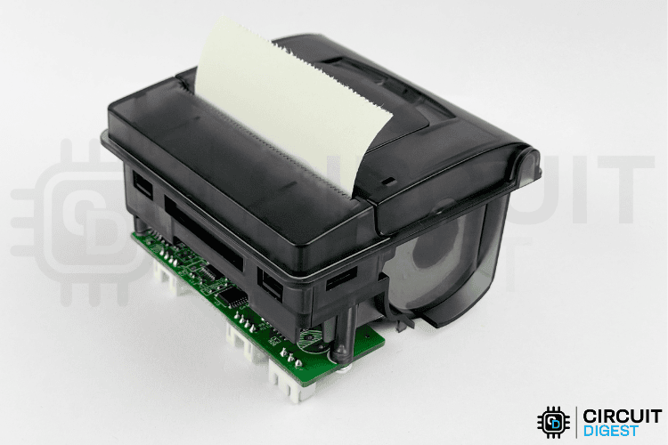
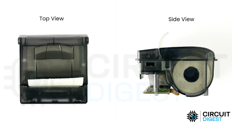
The PNP-500 is a compact, panel-mount thermal printer that's simple to use and highly reliable, making it a favourite for industrial and measurement applications. You'll often find it integrated into diagnostic equipment, control panels, and weighing scales, where space is tight and speed matters.
There is another printer available, the RS203, which is quite similar to the PNP-500. So, this ESP32 with thermal printer tutorial also works with the RS203 model.
⇒ Printing Method: Direct thermal line printing. This means it prints by selectively heating thermal paper. ⇒ Paper Width: 57mm, perfect for standard receipts and data logs. ⇒ Print Width: 48mm. ⇒ Print Speed: 50–80mm/sec, offering fast output for most needs. ⇒ Resolution: 8 dots/mm (384 dots/line), ensuring crisp text and barcodes. ⇒ Interfaces: Serial (RS232C, TTL) and USB, so you have options for how to connect. ⇒ Operating Voltage: 5–9V DC, and can handle up to 12V. ⇒ Dimensions: 76.8×77.4×47.6mm (WxDxH)—small enough to fit in tight control panels. ⇒ Max Paper Roll: 58mm wide, 40mm diameter, which covers most long-printing needs. ⇒ Print Head Life: Up to 50km of printing, so it's built to last.
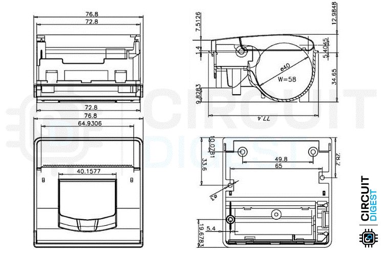
Dimensions of PNP500 Thermal Printer
The physical dimensions of this printer can be found in the image below.
With all these outlined dimensions, it's easy for you to plan the cutout for the enclosure in your project or 3d printable case, etc.
Hardware Overview of the PNP-500 Thermal Printer
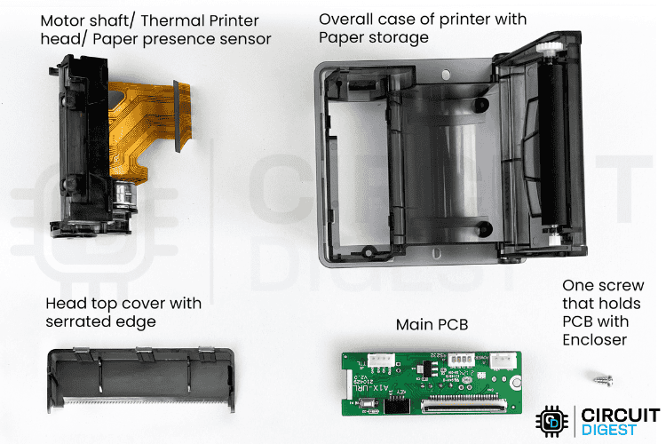
Now let’s do a deep dive into the hardware parts and their working. To make this clear, I have disassembled the printer completely so that everything is easy to understand. Below, you can see the fully disassembled PNP500
Be careful if you also plan to disassemble it for learning purposes. Make sure the plastic hinges are opened correctly, or they might break easily. This requires solid patience.
Now, let’s discuss more about the parts of the printer. This PNP-500 thermal printer has a total of 6 most important parts to understand. They are,
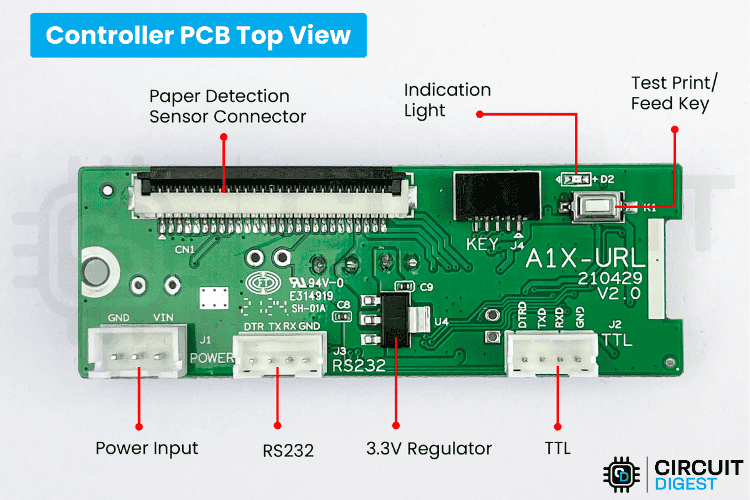
There is only one PCB in this printer that handles all the functions. So, let’s understand the PCB, starting from the top view.
In the image above with marked parts, you can identify the purpose of each I/O pin for interfacing a thermal printer with the ESP32 pinout. For communication, this module provides two options: RS232 and TTL. If you are using a microcontroller, the TTL port is very easy to integrate.
You can also find the power input pin. This supports a wide voltage range of 5V–9V, or 12V DC, as stated in the paper. However, I didn’t get perfect printing results with 5V. A voltage above 6V gave me the right darkness. Specifically, I used a 2S Li-ion battery pack to power the module.
Understanding how to use interfacing thermal printer with the ESP32 pinout makes it easier to get a perfect connection, and you can follow the complete wiring setup in the thermal printer ESP32 wiring diagram.
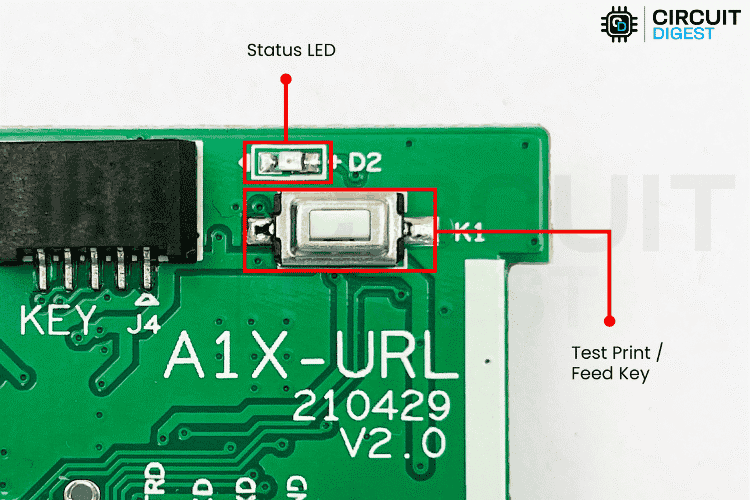
Next, there is an LED marked as D2, which is a status LED. Its status indicators are as follows:
Blinks once: Working properly
Blinks once: Working properly
Blinks twice: No printer detected
Blinks twice: No printer detected
Blinks three times: No paper detected
Blinks three times: No paper detected
Blinks five times: Printer mechanism is overheating
Blinks five times: Printer mechanism is overheating
Blinks ten times: No Chinese character stock IC detected
Blinks ten times: No Chinese character stock IC detected
Next, there is a button marked as K1. It has two functionalities:
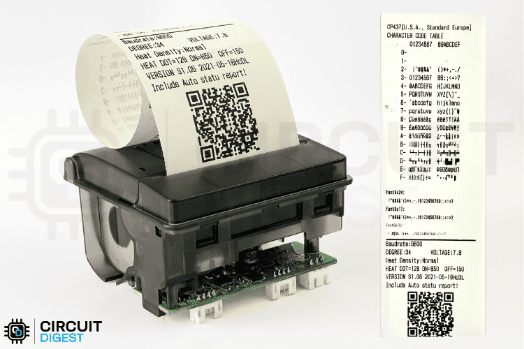
After pressing it while powering on the device, a test print page is printed, which looks like the following
First, the character code table is printed.
First, the character code table is printed.
Then, demo text for three font sizes is printed (9x24, 9x17, 8x16).
Then, demo text for three font sizes is printed (9x24, 9x17, 8x16).
Followed by information such as Baud rate, Degree (head temperature), Voltage, Heat Density (darkness of print), Heat Dot (number of heating elements activated simultaneously), ON/OFF timing, Firmware version, and finally, a QR code indicating \"QRCode Support!\".
Followed by information such as Baud rate, Degree (head temperature), Voltage, Heat Density (darkness of print), Heat Dot (number of heating elements activated simultaneously), ON/OFF timing, Firmware version, and finally, a QR code indicating \"QRCode Support!\".
In the image above, you can see the bottom view of the PCB. There are no I/O ports here—just the main ICs:
BY25D16 – A 16MB NOR-type Flash Memory, probably used to store important configuration data and large functions.
BY25D16 – A 16MB NOR-type Flash Memory, probably used to store important configuration data and large functions.
PT5139A – A dual H-Bridge motor driver IC used to drive the stepper motor for the paper feed mechanism.
PT5139A – A dual H-Bridge motor driver IC used to drive the stepper motor for the paper feed mechanism.
TPT3232E – An RS232 transceiver IC used for RS232 communication.
TPT3232E – An RS232 transceiver IC used for RS232 communication.
ARM-based 32-bit MCU – The exact model or part number is unknown, but it serves as the main processor of the printer, running on a 3.3V supply.
ARM-based 32-bit MCU – The exact model or part number is unknown, but it serves as the main processor of the printer, running on a 3.3V supply.
The print head is special, as it’s the main component responsible for the printing process. It’s a tiny mechanism. Practically, there are 384 individual heating elements, which produce 384 individual dots. You can see them in the image below. We verified the count ourselves to confirm it.
The print head already includes the required shift registers, embedded in the black region below the heating area, which is an IC. This helps reduce the number of control pins to just 6, along with additional GND and power pins.
This thermal print head also includes a thermistor for heat measurement. Along with this, there is a paper detection sensor and a servo motor that connect to the main PCB via the same ribbon cable.
Be careful with the ribbon cable; even though it’s flexible, it can tear easily.
Technologies used
Hardware components
- ESP32 Development Board (Any Model/Brand) – 1
- Thermal Printer (PNP-500 / RS203) – 1
- Resistors (1KΩ) – 2
- Connecting Wires – As Required
- Breadboard – 1
- 2S Li-Ion Battery – 1 (For powering the printer)
- Push Buttons – 2 (Optional)
What you get
- Working project / hardware kit, tested before delivery
- Complete source code with explanation
- Project demo and guidance for your viva
- Project report, PPT and IEEE paper support (on request)
Related Embedded projects

ESP32 Fingerprint Attendance System with Live Web Dashboard
Build a biometric attendance system using ESP32 with AS608 fingerprint sensor that logs attendance with timestamp to web dashboard and Googl...
View project
Mars Rover Robot Replica using ESP32 CAM and Arduino
Build a Mars Rover robot replica using ESP32-CAM and Arduino with a rocker-bogie suspension system, live video streaming, and smartphone app...
View project
ESP32 CAN Bus Tutorial Interfacing MCP2515 with ESP32
Learn CAN bus communication with ESP32 and MCP2515 CAN controller to send and receive data in automotive and industrial applications.
View project
ESP32 MP3 Music Player with SD Card and I2S Amplifier
Build a standalone ESP32 MP3 music player that reads audio from SD card and outputs high-quality audio via I2S DAC amplifier with web contro...
View project