Smart Ward Assistant: Low-Cost Patient Monitoring System
Low-cost ESP32-based Smart Ward Assistant for rural hospitals with wearable HR & SpO2 monitoring, real-time alerts, and centralized nurse station hub.
- Suitable forB.Tech Embedded students
- Build time3-4 weeks
- LevelIntermediate
- Available atAjvika Labs, Kakinada
About this project
Rural Primary Health Centers (PHCs) often face staff shortages, making continuous patient monitoring difficult, especially during night shifts. Critical changes in patient vitals such as Heart Rate (HR) and Oxygen Saturation (SpO2) can go unnoticed, leading to delayed medical intervention.
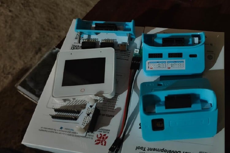
To address this challenge, I developed the Smart Ward Assistant, a low-cost, scalable patient monitoring system using ESP32 technology. The system consists of wearable vital monitoring tags for patients and a centralized smart hub at the nurse station. Patient vitals are monitored continuously and transmitted wirelessly to the hub, where alerts are generated instantly if abnormal conditions are detected. This system reduces manual workload, improves patient safety, and enables faster medical response in resource-limited healthcare environments.
Smart Alert & Display Hub
Wearable Patient Tag Connections
MAXREFDES117 Bio-Sensor → ESP32
Powered via 3.7V Li-Po battery
TP4056 module used for battery charging and protection
Smart Hub (ESP32-S3-BOX-3) Connections
Built-in Touch Display used for configuration
Built-in Microphone & Speaker used for voice alerts
External speaker connected for loud audio alerts (if required)
Wearable Patient Monitoring Tag
Connect the MAXREFDES117 sensor to the ESP32 using I²C pins.
Connect the Li-Po battery to the TP4056 charging module.
Power the ESP32 from the TP4056 output.
Secure all components on a small PCB or perfboard.
Place the assembled circuit inside a compact enclosure suitable for wrist or finger mounting.
Smart Alert & Display Hub
Place the ESP32-S3-BOX-3 at the nurse station.
Connect the SD card module for data logging.
Connect an external speaker if higher volume alerts are needed.
Power the BOX-3 using a USB adapter.
Verify wireless connectivity with all wearable tags.
Detailed Project Description
Smart Ward Assistant: Low-Cost Patient Monitoring System continuously measures the patient's vital signs and makes them visible in real time — on a local display and, over Wi-Fi, on a dashboard or phone — so that abnormal values trigger an alert instead of going unnoticed.
How It Works
1. The biomedical sensors are attached to the user and sampled by the microcontroller at a fixed rate.
2. Raw signals are filtered and converted into meaningful values (BPM, SpO2, temperature, ECG waveform).
3. Values are shown locally and pushed to the cloud/dashboard so a caregiver can watch remotely.
4. If a reading crosses a configured threshold, an alert (buzzer, app notification or message) is raised.
Key Components and Their Role
- ESP32: dual-core Wi-Fi + Bluetooth microcontroller that runs the firmware, reads the sensors and hosts the network connection.
- Bluetooth Low Energy: short-range low-power wireless link to a phone or browser.
- Li-ion battery + charger (TP4056): portable power with charge management.
Implementation Steps
1. Collect the components and study each module's datasheet (pin-out, voltage, interface).
2. Wire the circuit on a breadboard following the pin mapping; power sensors from the correct rail (3.3 V / 5 V).
3. Install ESP32, BLE, SPI and the required libraries; flash a minimal test sketch for each module separately.
4. Write the main firmware: read sensors → process → drive outputs / send data.
5. Configure network or cloud credentials and test communication end-to-end.
6. Calibrate thresholds, add error handling (reconnect, sensor time-out) and run a long-duration test.
7. Finalise on a PCB / enclosure and document wiring, code and results.
Key Features
- Real-time vital-sign readings
- Remote monitoring dashboard
- Threshold-based alerts
- Low-cost, portable hardware
Expected Output
On completion the student will have a live plot/table of vitals that updates every few seconds, with alerts when a limit is crossed.
Deliverables
- Complete source code with comments
- Circuit diagram and pin mapping
- Project report with screenshots and results
- Demonstration-ready build
To address this challenge, I developed the Smart Ward Assistant, a low-cost, scalable patient monitoring system using ESP32 technology. The system consists of wearable vital monitoring tags for patients and a centralized smart hub at the nurse station. Patient vitals are monitored continuously and transmitted wirelessly to the hub, where alerts are generated instantly if abnormal conditions are detected. This system reduces manual workload, improves patient safety, and enables faster medical response in resource-limited healthcare environments.
Smart Alert & Display Hub
Wearable Patient Tag Connections
MAXREFDES117 Bio-Sensor → ESP32
Powered via 3.7V Li-Po battery
TP4056 module used for battery charging and protection
Smart Hub (ESP32-S3-BOX-3) Connections
Built-in Touch Display used for configuration
Built-in Microphone & Speaker used for voice alerts
External speaker connected for loud audio alerts (if required)
Wearable Patient Monitoring Tag
Connect the MAXREFDES117 sensor to the ESP32 using I²C pins.
Connect the Li-Po battery to the TP4056 charging module.
Power the ESP32 from the TP4056 output.
Secure all components on a small PCB or perfboard.
Place the assembled circuit inside a compact enclosure suitable for wrist or finger mounting.
Smart Alert & Display Hub
Place the ESP32-S3-BOX-3 at the nurse station.
Connect the SD card module for data logging.
Connect an external speaker if higher volume alerts are needed.
Power the BOX-3 using a USB adapter.
Verify wireless connectivity with all wearable tags.
Detailed Project Description
Smart Ward Assistant: Low-Cost Patient Monitoring System continuously measures the patient's vital signs and makes them visible in real time — on a local display and, over Wi-Fi, on a dashboard or phone — so that abnormal values trigger an alert instead of going unnoticed.
How It Works
1. The biomedical sensors are attached to the user and sampled by the microcontroller at a fixed rate.
2. Raw signals are filtered and converted into meaningful values (BPM, SpO2, temperature, ECG waveform).
3. Values are shown locally and pushed to the cloud/dashboard so a caregiver can watch remotely.
4. If a reading crosses a configured threshold, an alert (buzzer, app notification or message) is raised.
Key Components and Their Role
- ESP32: dual-core Wi-Fi + Bluetooth microcontroller that runs the firmware, reads the sensors and hosts the network connection.
- Bluetooth Low Energy: short-range low-power wireless link to a phone or browser.
- Li-ion battery + charger (TP4056): portable power with charge management.
Implementation Steps
1. Collect the components and study each module's datasheet (pin-out, voltage, interface).
2. Wire the circuit on a breadboard following the pin mapping; power sensors from the correct rail (3.3 V / 5 V).
3. Install ESP32, BLE, SPI and the required libraries; flash a minimal test sketch for each module separately.
4. Write the main firmware: read sensors → process → drive outputs / send data.
5. Configure network or cloud credentials and test communication end-to-end.
6. Calibrate thresholds, add error handling (reconnect, sensor time-out) and run a long-duration test.
7. Finalise on a PCB / enclosure and document wiring, code and results.
Key Features
- Real-time vital-sign readings
- Remote monitoring dashboard
- Threshold-based alerts
- Low-cost, portable hardware
Expected Output
On completion the student will have a live plot/table of vitals that updates every few seconds, with alerts when a limit is crossed.
Deliverables
- Complete source code with comments
- Circuit diagram and pin mapping
- Project report with screenshots and results
- Demonstration-ready build
Technologies used
Hardware components
- ESP32
- LED
- Sensor
- Module
- Board
- Speaker
- Microphone
- PCB
- Battery
What you get
- Working project / hardware kit, tested before delivery
- Complete source code with explanation
- Project demo and guidance for your viva
- Project report, PPT and IEEE paper support (on request)
Delivery & Payment
Delivery takes a minimum of two weeks from the date your inquiry is confirmed.
Payment is in two parts:
• 50% advance to start the project
• Remaining 50% before delivery
Note:
• Documentation and PPT are not included by default
• If you need documentation/PPT, it can be arranged for extra time and cost
We'll confirm the exact timeline and cost with you after reviewing your requirements.
Related Embedded projects

Embedded
ESP32 Fingerprint Attendance System with Live Web Dashboard
Build a biometric attendance system using ESP32 with AS608 fingerprint sensor that logs attendance with timestamp to web dashboard and Googl...
View project
Embedded
Mars Rover Robot Replica using ESP32 CAM and Arduino
Build a Mars Rover robot replica using ESP32-CAM and Arduino with a rocker-bogie suspension system, live video streaming, and smartphone app...
View project
Embedded
ESP32 CAN Bus Tutorial Interfacing MCP2515 with ESP32
Learn CAN bus communication with ESP32 and MCP2515 CAN controller to send and receive data in automotive and industrial applications.
View project
Embedded
ESP32 MP3 Music Player with SD Card and I2S Amplifier
Build a standalone ESP32 MP3 music player that reads audio from SD card and outputs high-quality audio via I2S DAC amplifier with web contro...
View project