RFID Based Attendance System Using Arduino - Complete Project Guide
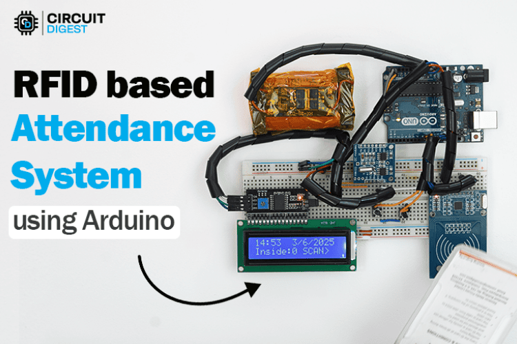
Learn to build an RFID based attendance system using Arduino with step-by-step instructions, circuit diagrams, and complete code. This $35 DIY project replaces expensive commercial systems with automatic check-in/check-out tracking, real-time LCD display, and offline data storage. Perfect for schools, offices, and industrial applications. Includes troubleshooting guide and future enhancement ideas.
- Suitable forB.Tech Embedded students
- Build time3-4 weeks
- LevelBeginner
- Available atAjvika Labs, Kakinada
About this project
In this comprehensive Arduino project, we'll guide you through building a complete RFID attendance system using Arduino that automatically detects check-ins and check-outs, displays real-time information on an LCD, and stores attendance logs with precise timestamps. Through our experience developing hundreds of electronics projects at CircuitDigest, we've designed this system to be both educational and practical - you'll master SPI and I2C communication, learn EEPROM data management, and create a professional-grade solution that can handle everything from office attendance to classroom management. By the end of this tutorial, you'll have a fully functional system that rivals commercial solutions costing hundreds of dollars.
RFID Attendance System using Arduino - Quick Overview
Build Time: 4-6 hours | Cost: $25-35 | Difficulty: Beginner-Intermediate
What You'll Learn: SPI/I2C communication, EEPROM storage, Real-time clock programming, RFID card management
Applications: Office attendance, Student tracking, Access control, Visitor management
Why Choose Arduino for RFID Attendance Systems?
Step-by-Step Assembly Guide
Adding Personal Data to RFID Cards
Project Demonstration
Frequently Asked Questions
Troubleshooting Guide
Future Enhancements and Upgrades
Other Projects using RFID Module
Why Choose Arduino for RFID Attendance Systems?
This RFID-based attendance system using an Arduino project, offers superior reliability compared to commercial solutions. The Arduino platform provides cost-effective customisation, while the MFRC522 RFID module ensures accurate card detection. Our system features automatic check-in/check-out detection, real-time clock integration, and persistent data storage that remains intact even during power outages. More than that, what is more fun than building your attendance system and having it used daily by your colleagues or student friends? This is not only a simple DIY RFID attendance tracker, but also opens room to future enhancements like IoT integration, wireless attendance monitoring, and much more.
Arduino RFID Attendance System Features
This simple DIY Arduino attendance system can track student and employee attendance, manage access to libraries or meeting rooms, and monitor visitor entries. In workshops, gyms, or community centers, it ensures accurate logging and helps with usage tracking. Industrial setups can benefit from features like shift monitoring, worker safety tracking, and contractor management. This contactless attendance system ensures hygiene compliance while providing accurate employee time tracking and student attendance monitoring capabilities.
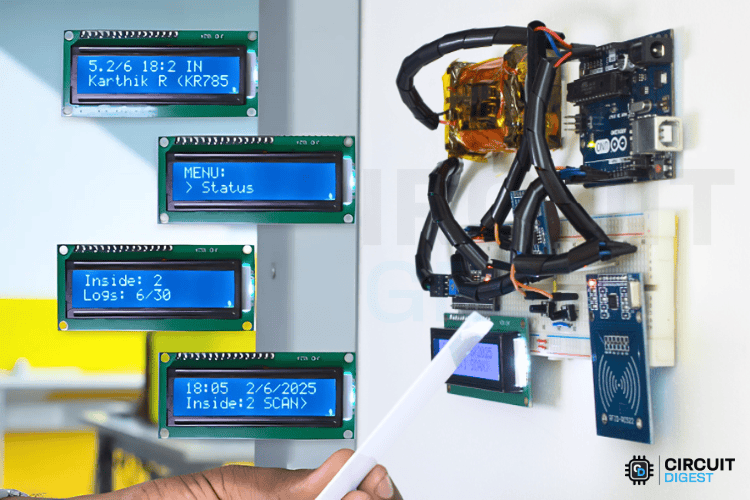
At its core, the system offers automatic check-in/check-out detection, real-time timestamping using an RTC module, and reliable data storage even during power loss. A user-friendly LCD interface provides real-time updates, while advanced features like live people count, scrolling name display, RFID-based access control, and automatic log management make the system smart and efficient. It can be operated either via physical buttons or through the serial monitor for added flexibility.
Components Required for the RFID Attendance System
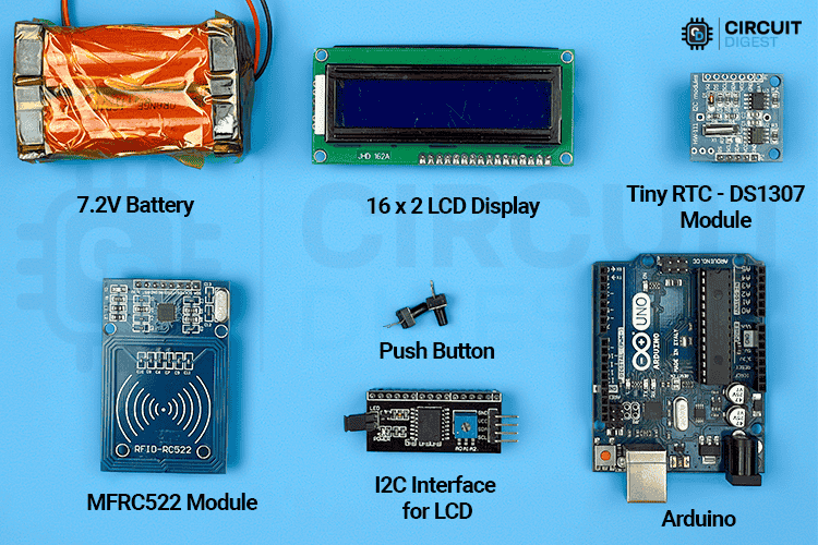
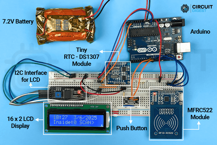
Arduino Uno (x1): Microcontroller board with ATmega328P, operates at 5V. Perfect for RFID-based projects and Arduino attendance tracking systems.
Arduino Uno (x1): Microcontroller board with ATmega328P, operates at 5V. Perfect for RFID-based projects and Arduino attendance tracking systems.
RFID Reader MFRC522 Module(x1): 13.56MHz RFID reader with SPI interface, supports read/write operations.
RFID Reader MFRC522 Module(x1): 13.56MHz RFID reader with SPI interface, supports read/write operations.
Tiny RTC DS1307 Module (x1): Real-time clock with I2C interface and CR2032 battery backup. It also has an AT24C32 EEPROM IC (32KB external memory module using I2C interface) in it.
Tiny RTC DS1307 Module (x1): Real-time clock with I2C interface and CR2032 battery backup. It also has an AT24C32 EEPROM IC (32KB external memory module using I2C interface) in it.
16x2 I2C LCD Display (x1): HD44780-compatible character display with blue backlight and I2C backpack.
16x2 I2C LCD Display (x1): HD44780-compatible character display with blue backlight and I2C backpack.
Push Buttons (x2): 6x6mm tactile buttons, normally open, used for user input. RFID Cards/Tags (Required): Mifare Classic 1K, 13.56MHz, with 1KB memory for each card/tag.
Push Buttons (x2): 6x6mm tactile buttons, normally open, used for user input. RFID Cards/Tags (Required): Mifare Classic 1K, 13.56MHz, with 1KB memory for each card/tag.
Breadboard (x1): Full-size breadboard for easy prototyping and circuit connections.
Breadboard (x1): Full-size breadboard for easy prototyping and circuit connections.
Jumper Wires (Required): Male-to-male and female connectors for wiring components.
Jumper Wires (Required): Male-to-male and female connectors for wiring components.
Power Supply (x1): 5V–12V DC adapter for powering the Arduino, or in my case, we use 2S Lithium-ion battery connecting to the Vin pin.
Power Supply (x1): 5V–12V DC adapter for powering the Arduino, or in my case, we use 2S Lithium-ion battery connecting to the Vin pin.
RFID Attendance System Circuit Diagram
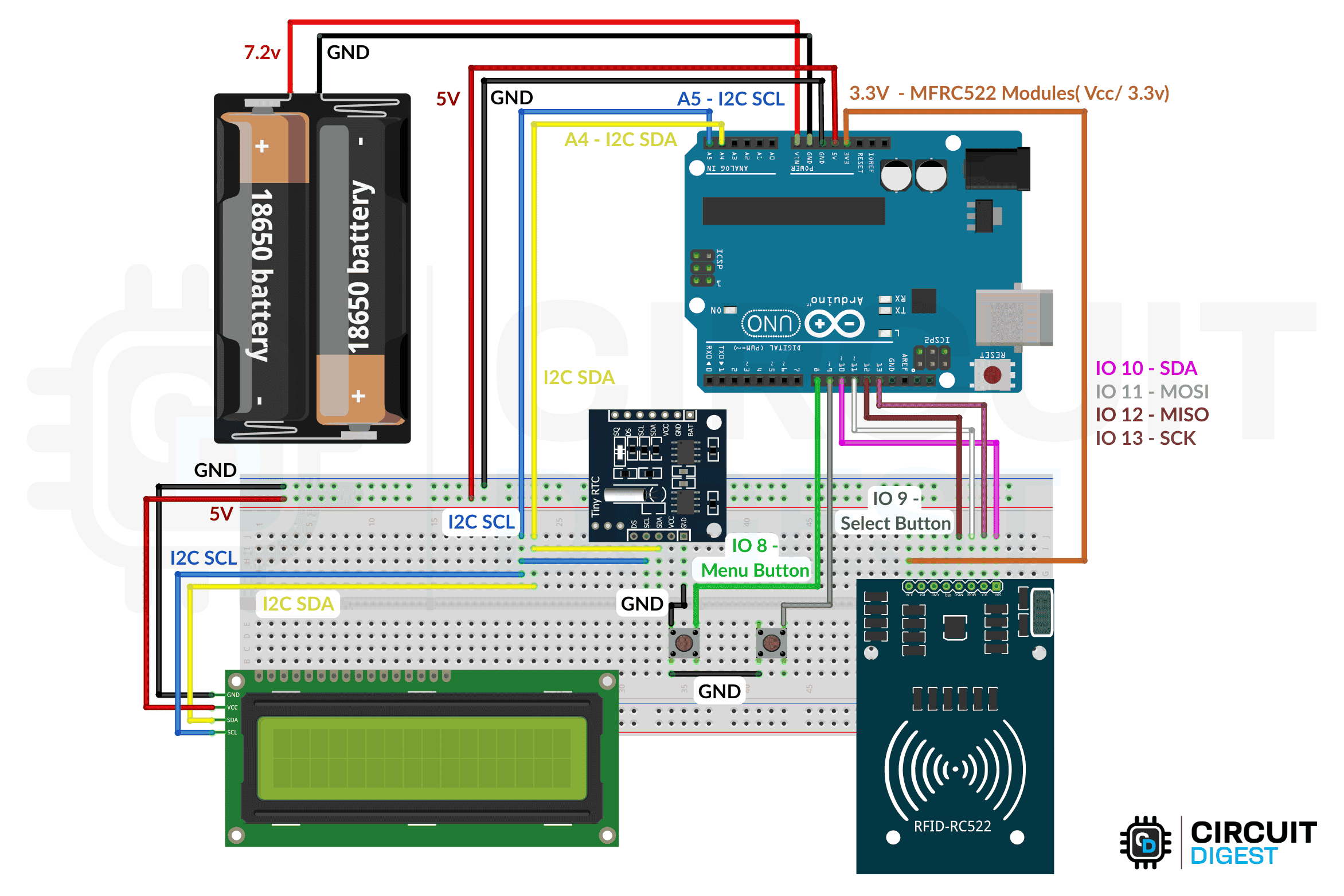
Below you can see the circuit diagram used in the RFID attendance system project. If you are completely new to using RFID, you can check out this tutorial on interfacing RC522 RFID module with Arduino, where we explore the basics of RFID technology with Arduino and how it works with microcontrollers.
All components operate at 5V, with the Arduino providing regulated power to all modules. The I2C bus operates at 5V logic levels, while the RFID reader uses 3.3V internally but is 5V tolerant. The system employs multiple communication protocols to interface with various peripherals. The SPI (Serial Peripheral Interface) protocol is used exclusively for communicating with the MFRC522 RFID reader, ensuring high-speed data transfer.
The system utilises multiple I2C devices, each with a specific address for communication. The 16x2 I2C LCD display is assigned the address 0x27 and serves as the main output interface. The DS1307 Real-Time Clock (RTC) module, operating at address 0x68, keeps track of time, while the AT24C32 EEPROM module, addressed at 0x50, is used for data storage purposes.
For user interaction, simple digital I/O is used to read inputs from push buttons. Now let's see the detailed wiring connection used in the RFID attendance tracker system, starting from the Arduino UNO.
Controls reader reset, Optional
INPUT_PULLUP enabled
INPUT_PULLUP enabled
The MFRC522 RFID reader is connected to the Arduino Uno with VCC (3.3V) to 3.3V, GND to GND, RST to digital pin 7, SDA (SS) to digital pin 10, MOSI to pin 11, MISO to pin 12, and SCK to pin 13.
The DS1307 RTC module contains both the DS1307 and AT24C32 EEPROMs. So, connect both via I2C, with VCC to 5V, GND to GND, SDA to analog pin A4, and SCL to analog pin A5. The same applies to the I2C LCD.
Additionally, the user interface is equipped with two push buttons: a \" Menu \" button connected between digital pin 8 and GND, and a \" Select \" button connected between digital pin 9 and GND. Both buttons make use of internal pull-up resistors configured in the code.
Step-by-Step Arduino RFID System Assembly Guide
Place your Arduino next to the breadboard for easy access. Use a red wire to connect the Arduino's 5V pin to the breadboard's positive power rail, and a black wire to connect the Arduino's GND pin to the breadboard's negative power rail. This creates your main power distribution for all components.
Plug the RFID module into the breadboard with enough space around it. Connect the VCC pin to the Arduino's 3.3V (not 5V), and GND to the ground rail. For the data connections, wire SDA to Pin 10, SCK to Pin 13, MOSI to Pin 11, MISO to Pin 12, and RST to Pin 9.
Wire your LCD display to the Arduino using the I2C connection. Connect VCC to the 5V power rail, GND to the ground rail, SDA to Pin A4, and SCL to Pin A5. The LCD should now share the same I2C bus that other devices will use.
Connect the RTC module to the same I2C bus as the LCD. Wire VCC to the 5V power rail, GND to the ground rail, SDA to Pin A4 (same connection as LCD), and SCL to Pin A5 (same connection as LCD). Both devices can share these I2C lines.
Insert two push buttons on the breadboard in convenient locations. For each button, connect one terminal to the ground rail and the other terminal to a digital pin on the Arduino. Connect the first button to Pin 8 and the second button to Pin 7.
Double-check all your connections against the circuit diagram. Make sure every component has proper power and ground connections, and that no wires are loose or touching each other. Connect the USB cable from your computer to the Arduino to provide power and programming capability.
Upload a simple test program to verify all components are working. The LCD should display text, the RFID reader should detect cards, and the buttons should respond when pressed. If everything works, your assembly is complete and ready for the main program.
Remember: This assembly is suited for both updating the card data and running the main attendance logger program.
Arduino Code for RFID-Based Attendance System
The GitHub repository contains everything needed for the project, including the main attendance system code that manages RFID scanning, logging, and user feedback; a card programming utility to write and manage personal data like name and ID on RFID cards; and complete documentation with circuit diagrams to guide users through hardware setup and system integration.
Let’s begin with the Code,
SPI: Handles communication with the RFID reader (Built-in Library)
SPI: Handles communication with the RFID reader (Built-in Library)
MFRC522: Library for interfacing with the MFRC522 RFID module.
MFRC522: Library for interfacing with the MFRC522 RFID module.
Wire: Supports I2C communication for RTC, EEPROM, and LCD. (Built-in Library)
Wire: Supports I2C communication for RTC, EEPROM, and LCD. (Built-in Library)
RTClib : Manages the DS1307 Real-Time Clock module.
RTClib : Manages the DS1307 Real-Time Clock module.
LiquidCrystal_I2C: Used to control a 16x2 LCD via I2C.
LiquidCrystal_I2C: Used to control a 16x2 LCD via I2C.
Pin definitions establish the hardware connections, with RST_PIN and SS_PIN configured for RFID communication, and BUTTON_MENU and BUTTON_SELECT pins set up for user interface navigation.
Initialises objects for RFID, RTC, LCD, and the default RFID key.
Data storage constants define the RFID card memory layout, with NAME_START_BLOCK and ID_START_BLOCK specifying where personal information is stored on cards.
Maximum lengths for names and IDs are set, along with log storage parameters including MAX_LOGS for total entries and LOG_SIZE for individual record size. These are customizable.
System state variables track the current number of stored logs, people currently inside the facility, and various timing and navigation states.
These values are customizable, but must be updated in both the main and personal data utility code for consistency.
The MenuState enumeration defines different screen modes, including home display, log viewing, status checking, log clearing, and time setting. Navigation variables manage menu indexing, button debouncing, LCD update timing, and scrolling text animation parameters.
The setup function runs once when the Arduino powers on and gets everything ready to work.
It starts serial communication so you can see debug messages on your computer, then configures the button pins to use internal pull-up resistors. This means the buttons read as HIGH normally and LOW when pressed.
The LCD display gets initialised and shows a startup message while other components are being prepared. The system starts SPI communication for the RFID reader, initialises the RFID module itself, and begins I2C communication for the clock and memory chip.
One critical check happens here - if the real-time clock doesn't respond properly, the system stops completely. This makes sense because accurate timestamps are essential for an attendance system. The RFID security key gets set to the default values that work with most MIFARE cards.
Technologies used
Hardware components
- 16x2 I2C LCD Display(x1):HD44780-compatible character display with blue backlight and I2C backpack.
- Breadboard (x1):Full-size breadboard for easy prototyping and circuit connections.
- Jumper Wires (Required):Male-to-male and female connectors for wiring components.
Project demo video
What you get
- Working project / hardware kit, tested before delivery
- Complete source code with explanation
- Project demo and guidance for your viva
- Project report, PPT and IEEE paper support (on request)
Related Embedded projects

ESP32 Fingerprint Attendance System with Live Web Dashboard
Build a biometric attendance system using ESP32 with AS608 fingerprint sensor that logs attendance with timestamp to web dashboard and Googl...
View project
Mars Rover Robot Replica using ESP32 CAM and Arduino
Build a Mars Rover robot replica using ESP32-CAM and Arduino with a rocker-bogie suspension system, live video streaming, and smartphone app...
View project
ESP32 CAN Bus Tutorial Interfacing MCP2515 with ESP32
Learn CAN bus communication with ESP32 and MCP2515 CAN controller to send and receive data in automotive and industrial applications.
View project
ESP32 MP3 Music Player with SD Card and I2S Amplifier
Build a standalone ESP32 MP3 music player that reads audio from SD card and outputs high-quality audio via I2S DAC amplifier with web contro...
View project