
NeuroBand: The Smart Safety Band
NeuroBand is an AI-powered smart safety armband with fall detection, ECG, heart rate monitoring, and real-time SOS alerts for elderly and high-risk individuals.
- Suitable forM.Tech Embedded students
- Build time3-4 weeks
- LevelBeginner
- Available atAjvika Labs, Kakinada
About this project
By Kartik Khandelwal
Core Purpose: NeuroBand is a specialized smart safety armband engineered to provide timely assistance to elderly and high-risk individuals during emergencies. Its primary goal is to mitigate the risks associated with falls and medical crises while simultaneously addressing the industry-wide challenge of frequent false alarms. The Global Context of Falls:
Global Impact: Falls are a critical public health issue. According to the World Health Organization (WHO), approximately 684,000 fatal falls occur globally each year, making it the second leading cause of unintentional injury death, after road traffic injuries [1].
Regional Burden: The impact is disproportionately high in low- and middle-income regions. In India, research indicates that approximately one-third of older adults experience a fall at some point, highlighting the urgent need for reliable safety solutions [2].
The Critical Factor: In many fall incidents, the severity of the outcome is often dictated not by the fall itself, but by the \"long lie\"—the delay in receiving medical attention. NeuroBand aims to bridge this gap by ensuring rapid response.
Addressing Current Limitations:
The False Alarm Problem: Traditional safety wearables often rely on binary triggers, such as a simple acceleration spike or a panic button. These mechanisms frequently misinterpret daily actions—like sitting down abruptly or dropping the device—as emergencies.
Consequences: Frequent false positives lead to \"alarm fatigue,\" causing caregivers to distrust alerts and potentially ignore genuine emergencies.
NeuroBand’s Solution: Unlike single-trigger devices, NeuroBand employs a contextual approach. It continuously observes multiple signal streams to cross-verify data, ensuring that an alert is only triggered when a genuine threat is detected.
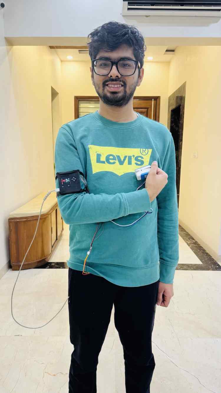
NeuroBand utilizes a cohesive system design that merges advanced hardware sensing with a robust software framework.
Motion Sensing: The device is equipped with high-fidelity accelerometers and gyroscopes to map user activity, posture, and sudden orientation changes.
Heart Rate Monitoring: Continuous optical sensors track cardiovascular stability, providing a baseline for the user's normal physiological state.
ECG Integration: The inclusion of an ECG (Electrocardiogram) sensor allows the device to capture detailed electrical heart activity, offering a deeper diagnostic view than standard pulse trackers.
Data Fusion: By combining physical movement data with physiological responses, the hardware provides a holistic view of the user's status (e.g., distinguishing a stumble from a syncopal fall caused by a heart condition).
Real-Time Operating System (RTOS): The device runs on an RTOS, which allows for deterministic and parallel task management. This ensures that critical safety tasks are never blocked by background processes.
Task Prioritization: The software architecture creates a hierarchy where emergency detection and user interaction are treated as high-priority tasks, while data logging and routine monitoring run in the background.
Signal Processing: Raw sensor data is subjected to advanced filtering and smoothing algorithms. This pre-processing step eliminates sensor noise and short-term artifacts associated with normal daily movement, preventing false triggers.
Resource Synchronization: To maintain system stability, shared resources—such as sensor communication buses and memory buffers for ECG data—are managed via strict synchronization protocols to prevent data corruption.
System Flow and Communication
The operational logic of NeuroBand is designed to transition smoothly between monitoring, evaluation, and emergency response.
Background Operation: The device operates unobtrusively, logging motion, heart rate, and ECG signals without user intervention.
Pattern Evaluation: Instead of reacting to instantaneous spikes, the system analyzes trends. For example, a sudden motion spike is flagged as a \"potential\" fall, but the system checks subsequent data (like a period of immobility or abnormal heart rate) before confirming.
Lightweight Communication: During this phase, the device uses a low-bandwidth messaging protocol to send periodic \"heartbeat\" updates (activity status, battery level) to the mobile app, ensuring the system is online without draining the battery.
Trigger Conditions: The system enters a high-alert state if it detects:
A manual SOS request from the user.
Repeated fall-like motion signatures.
Sustained abnormal vital signs (e.g., bradycardia or tachycardia) following a motion event.
Contextual Verification: By cross-referencing the motion event with the heart rate recovery, the device filters out non-emergencies (e.g., a user tripping but recovering immediately).
Immediate Alerts: Upon confirming a high-risk situation, NeuroBand activates \"HELP Mode.\"
Audible Alarm: A loud SOS siren is played on the device to alert anyone in the immediate vicinity.
Remote Notification: Simultaneously, critical alerts are pushed over WiFi to the caregiver's mobile app. Crucially, this packet includes a snippet of recent ECG data recorded just prior to the event, providing medical context.
User Control: The user retains the ability to cancel the alarm if the trigger was accidental, maintaining their agency and reducing unnecessary panic.
Phase 4: Caregiver Dashboard
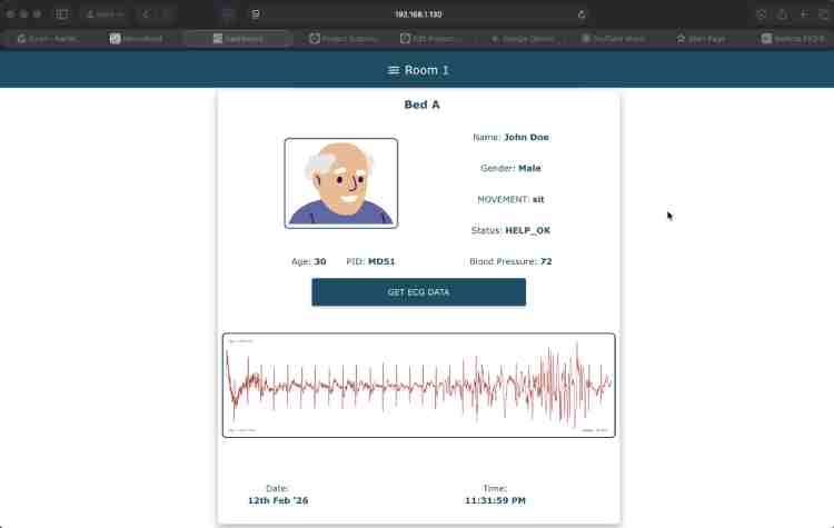
Live Telemetry: Caregivers access a centralized dashboard displaying live vital signs and current activity status.
Incident Context: In the event of an alarm, the dashboard highlights the specific trigger and presents the recorded ECG data, allowing caregivers or medical professionals to assess the severity of the incident remotely before dispatching help.
World Health Organization. (2021). Falls: Key Facts. Retrieved from https://www.who.int/news-room/fact-sheets/detail/falls
Sirohi, A., et al. (2017). Epidemiology of falls and its risk factors among elders in a rural area of Coimbatore, India. International Journal of Community Medicine and Public Health. (Noting prevalence rates of falls among Indian older adults are often estimated at around 31-33%).
Video depicting IOS App
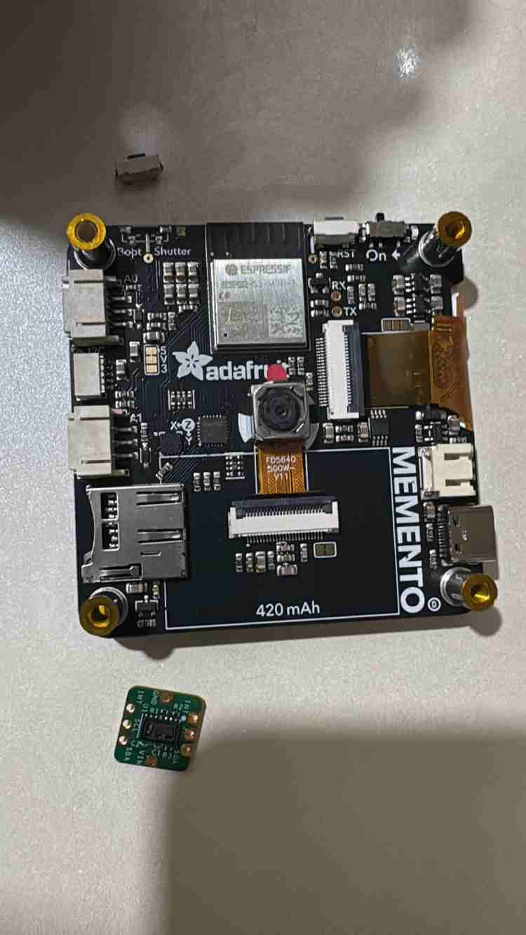
MEMENTO Programmable Camera
MAXREFDES117 Bio-Sensor
Adafruit STEMMA QT Cable
Jumper Cables (M-M, M-F)
3D Printed Models ( 1 + 1 )
Spiral Cable Protector
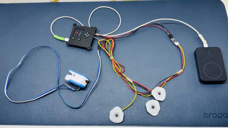
The system utilizes two primary modalities for cardiac monitoring:
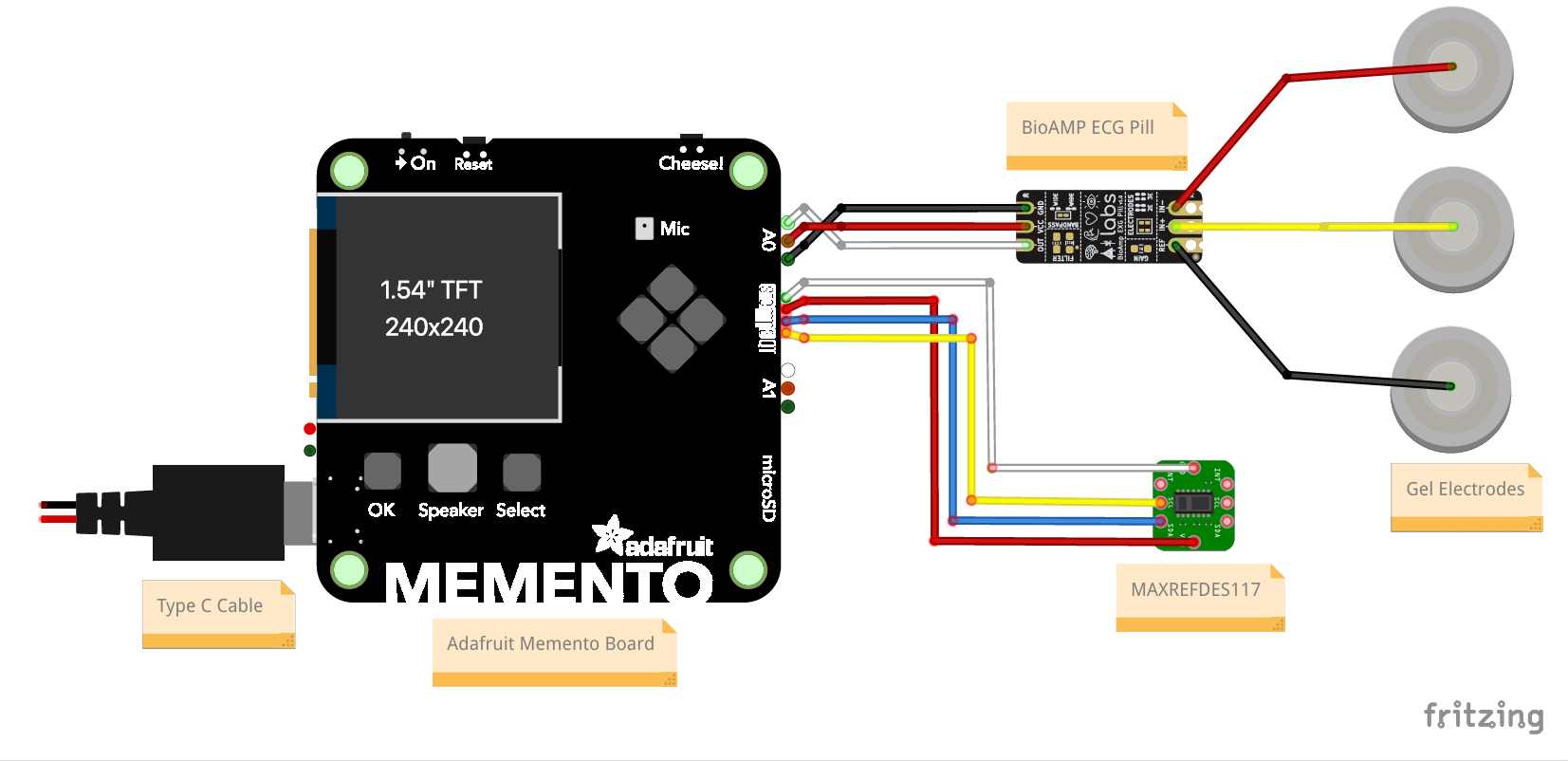
Biopotential Acquisition: An UpsideDown Labs BioAMP-EXG Pill is interfaced via Analog Port 0 (A0) to capture raw ECG data.
Optical Heart Rate Monitoring: A MAXREFDES117 Bio-Sensor is connected via the I2C bus to provide heart rate measurements.
Due to the high current demands of the system exceeding 1500mA, a standard LiPo battery was insufficient. This significant load is driven by:
On-board Neural Network inference.
Active Wi-Fi telemetry.
Simultaneous operation of multiple peripherals.
To ensure stable operation and provide sufficient current overhead, a high-capacity Battery Bank was utilized as the primary power source.
Design Documentation
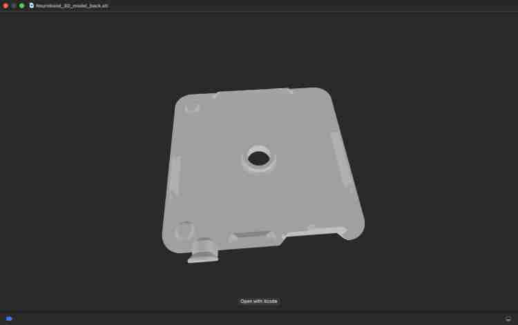
The system architecture, including the full circuit schematic and component interconnects, was designed and documented using Fritzing and all the changes in existing 3D models were made using Solidworks.
Step 1: Creating the Design
I started with a design from Adafruit called [Design A] (see Figure 1). However, I realized it needed some changes to fit our project better:
Better Hangers: I made the corner hangers bigger and added more so the band stays on securely (Figure 2).
New Holes: I added specific holes (slots) for the I2C and A0 cables so everything connects easily (Figure 2).
Big thanks to my friend Utkarsh for helping with these changes!
Step 2: Printing the Parts
I ordered the parts from Robu.in. If you are ordering yours, upload both part files and use these settings (Figure 3):
Material: PLA - Black
Quality: Standard (0.2 mm)
Step 1: Preparing the Wires
The Cable: The Adafruit cable comes with plugs on both ends. Cut one plug off.
Soldering: Strip the plastic off the cut wires and solder them to female jumper wires.
Protection: Cover the soldered joints with heat shrink tubes so the wires don't touch each other (Figure 4).
The Board: Cut a small piece of Zero PCB. It should be the same size as the sensor, plus two extra holes on each side. Solder pins onto this board (Figure 5).
Step 2: Modifying the Case
Cutting: Cut a hole in the plastic oximeter case. Be very careful not to cut the spring inside! (Figure 6).
Gluing: Put the sensor inside the hole you just made. Use a glue gun to hold it tight so it doesn't move (Figure 7).
Step 3: Connecting It
Plug the cable into the I2C port on the main board.
Check This: Make sure the Power (VCC) and Ground (GND) wires match the diagram before turning it on (Figure 8).
Step 1: Preparing the Cable
Take the 3-pin cable. Just like before, cut one end off.
Solder the cut wires to female jumper wires and cover them with heat shrink tubes (Figure 9).
Step 2: Connecting It
Plug the uncut end into the BioAmp EXG board.
Plug the soldered end into the A0 port on the main board.
Core Purpose: NeuroBand is a specialized smart safety armband engineered to provide timely assistance to elderly and high-risk individuals during emergencies. Its primary goal is to mitigate the risks associated with falls and medical crises while simultaneously addressing the industry-wide challenge of frequent false alarms. The Global Context of Falls:
Global Impact: Falls are a critical public health issue. According to the World Health Organization (WHO), approximately 684,000 fatal falls occur globally each year, making it the second leading cause of unintentional injury death, after road traffic injuries [1].
Regional Burden: The impact is disproportionately high in low- and middle-income regions. In India, research indicates that approximately one-third of older adults experience a fall at some point, highlighting the urgent need for reliable safety solutions [2].
The Critical Factor: In many fall incidents, the severity of the outcome is often dictated not by the fall itself, but by the \"long lie\"—the delay in receiving medical attention. NeuroBand aims to bridge this gap by ensuring rapid response.
Addressing Current Limitations:
The False Alarm Problem: Traditional safety wearables often rely on binary triggers, such as a simple acceleration spike or a panic button. These mechanisms frequently misinterpret daily actions—like sitting down abruptly or dropping the device—as emergencies.
Consequences: Frequent false positives lead to \"alarm fatigue,\" causing caregivers to distrust alerts and potentially ignore genuine emergencies.
NeuroBand’s Solution: Unlike single-trigger devices, NeuroBand employs a contextual approach. It continuously observes multiple signal streams to cross-verify data, ensuring that an alert is only triggered when a genuine threat is detected.
NeuroBand utilizes a cohesive system design that merges advanced hardware sensing with a robust software framework.
Motion Sensing: The device is equipped with high-fidelity accelerometers and gyroscopes to map user activity, posture, and sudden orientation changes.
Heart Rate Monitoring: Continuous optical sensors track cardiovascular stability, providing a baseline for the user's normal physiological state.
ECG Integration: The inclusion of an ECG (Electrocardiogram) sensor allows the device to capture detailed electrical heart activity, offering a deeper diagnostic view than standard pulse trackers.
Data Fusion: By combining physical movement data with physiological responses, the hardware provides a holistic view of the user's status (e.g., distinguishing a stumble from a syncopal fall caused by a heart condition).
Real-Time Operating System (RTOS): The device runs on an RTOS, which allows for deterministic and parallel task management. This ensures that critical safety tasks are never blocked by background processes.
Task Prioritization: The software architecture creates a hierarchy where emergency detection and user interaction are treated as high-priority tasks, while data logging and routine monitoring run in the background.
Signal Processing: Raw sensor data is subjected to advanced filtering and smoothing algorithms. This pre-processing step eliminates sensor noise and short-term artifacts associated with normal daily movement, preventing false triggers.
Resource Synchronization: To maintain system stability, shared resources—such as sensor communication buses and memory buffers for ECG data—are managed via strict synchronization protocols to prevent data corruption.
System Flow and Communication
The operational logic of NeuroBand is designed to transition smoothly between monitoring, evaluation, and emergency response.
Background Operation: The device operates unobtrusively, logging motion, heart rate, and ECG signals without user intervention.
Pattern Evaluation: Instead of reacting to instantaneous spikes, the system analyzes trends. For example, a sudden motion spike is flagged as a \"potential\" fall, but the system checks subsequent data (like a period of immobility or abnormal heart rate) before confirming.
Lightweight Communication: During this phase, the device uses a low-bandwidth messaging protocol to send periodic \"heartbeat\" updates (activity status, battery level) to the mobile app, ensuring the system is online without draining the battery.
Trigger Conditions: The system enters a high-alert state if it detects:
A manual SOS request from the user.
Repeated fall-like motion signatures.
Sustained abnormal vital signs (e.g., bradycardia or tachycardia) following a motion event.
Contextual Verification: By cross-referencing the motion event with the heart rate recovery, the device filters out non-emergencies (e.g., a user tripping but recovering immediately).
Immediate Alerts: Upon confirming a high-risk situation, NeuroBand activates \"HELP Mode.\"
Audible Alarm: A loud SOS siren is played on the device to alert anyone in the immediate vicinity.
Remote Notification: Simultaneously, critical alerts are pushed over WiFi to the caregiver's mobile app. Crucially, this packet includes a snippet of recent ECG data recorded just prior to the event, providing medical context.
User Control: The user retains the ability to cancel the alarm if the trigger was accidental, maintaining their agency and reducing unnecessary panic.
Phase 4: Caregiver Dashboard
Live Telemetry: Caregivers access a centralized dashboard displaying live vital signs and current activity status.
Incident Context: In the event of an alarm, the dashboard highlights the specific trigger and presents the recorded ECG data, allowing caregivers or medical professionals to assess the severity of the incident remotely before dispatching help.
World Health Organization. (2021). Falls: Key Facts. Retrieved from https://www.who.int/news-room/fact-sheets/detail/falls
Sirohi, A., et al. (2017). Epidemiology of falls and its risk factors among elders in a rural area of Coimbatore, India. International Journal of Community Medicine and Public Health. (Noting prevalence rates of falls among Indian older adults are often estimated at around 31-33%).
Video depicting IOS App
MEMENTO Programmable Camera
MAXREFDES117 Bio-Sensor
Adafruit STEMMA QT Cable
Jumper Cables (M-M, M-F)
3D Printed Models ( 1 + 1 )
Spiral Cable Protector
The system utilizes two primary modalities for cardiac monitoring:
Biopotential Acquisition: An UpsideDown Labs BioAMP-EXG Pill is interfaced via Analog Port 0 (A0) to capture raw ECG data.
Optical Heart Rate Monitoring: A MAXREFDES117 Bio-Sensor is connected via the I2C bus to provide heart rate measurements.
Due to the high current demands of the system exceeding 1500mA, a standard LiPo battery was insufficient. This significant load is driven by:
On-board Neural Network inference.
Active Wi-Fi telemetry.
Simultaneous operation of multiple peripherals.
To ensure stable operation and provide sufficient current overhead, a high-capacity Battery Bank was utilized as the primary power source.
Design Documentation
The system architecture, including the full circuit schematic and component interconnects, was designed and documented using Fritzing and all the changes in existing 3D models were made using Solidworks.
Step 1: Creating the Design
I started with a design from Adafruit called [Design A] (see Figure 1). However, I realized it needed some changes to fit our project better:
Better Hangers: I made the corner hangers bigger and added more so the band stays on securely (Figure 2).
New Holes: I added specific holes (slots) for the I2C and A0 cables so everything connects easily (Figure 2).
Big thanks to my friend Utkarsh for helping with these changes!
Step 2: Printing the Parts
I ordered the parts from Robu.in. If you are ordering yours, upload both part files and use these settings (Figure 3):
Material: PLA - Black
Quality: Standard (0.2 mm)
Step 1: Preparing the Wires
The Cable: The Adafruit cable comes with plugs on both ends. Cut one plug off.
Soldering: Strip the plastic off the cut wires and solder them to female jumper wires.
Protection: Cover the soldered joints with heat shrink tubes so the wires don't touch each other (Figure 4).
The Board: Cut a small piece of Zero PCB. It should be the same size as the sensor, plus two extra holes on each side. Solder pins onto this board (Figure 5).
Step 2: Modifying the Case
Cutting: Cut a hole in the plastic oximeter case. Be very careful not to cut the spring inside! (Figure 6).
Gluing: Put the sensor inside the hole you just made. Use a glue gun to hold it tight so it doesn't move (Figure 7).
Step 3: Connecting It
Plug the cable into the I2C port on the main board.
Check This: Make sure the Power (VCC) and Ground (GND) wires match the diagram before turning it on (Figure 8).
Step 1: Preparing the Cable
Take the 3-pin cable. Just like before, cut one end off.
Solder the cut wires to female jumper wires and cover them with heat shrink tubes (Figure 9).
Step 2: Connecting It
Plug the uncut end into the BioAmp EXG board.
Plug the soldered end into the A0 port on the main board.
Technologies used
Hardware components
- LED
- Button
- Sensor
- Board
- Camera
- PCB
- Battery
Software & tools
- Fritzing
Project demo video
What you get
- Working project / hardware kit, tested before delivery
- Complete source code with explanation
- Project demo and guidance for your viva
- Project report, PPT and IEEE paper support (on request)
Delivery & Payment
Delivery takes a minimum of two weeks from the date your inquiry is confirmed.
Payment is in two parts:
• 50% advance to start the project
• Remaining 50% before delivery
Note:
• Documentation and PPT are not included by default
• If you need documentation/PPT, it can be arranged for extra time and cost
We'll confirm the exact timeline and cost with you after reviewing your requirements.
Related Embedded projects

Embedded
ESP32 Fingerprint Attendance System with Live Web Dashboard
Build a biometric attendance system using ESP32 with AS608 fingerprint sensor that logs attendance with timestamp to web dashboard and Googl...
View project
Embedded
Mars Rover Robot Replica using ESP32 CAM and Arduino
Build a Mars Rover robot replica using ESP32-CAM and Arduino with a rocker-bogie suspension system, live video streaming, and smartphone app...
View project
Embedded
ESP32 CAN Bus Tutorial Interfacing MCP2515 with ESP32
Learn CAN bus communication with ESP32 and MCP2515 CAN controller to send and receive data in automotive and industrial applications.
View project
Embedded
ESP32 MP3 Music Player with SD Card and I2S Amplifier
Build a standalone ESP32 MP3 music player that reads audio from SD card and outputs high-quality audio via I2S DAC amplifier with web contro...
View project