

Interfacing SD Card Module with Raspberry Pi Pico
Learn to interface Raspberry Pi Pico SD Card Moduleusing SPI. Complete wiring guide, Arduino code, FAT32 setup, file operations & troubleshooting included
- Suitable forB.Tech Embedded students
- Build time3-4 weeks
- LevelBeginner
- Available atAjvika Labs, Kakinada
About this project
The Raspberry Pi Pico SD card module is a simple yet very handy add-on that lets you store and access a lot of data using a standard microSD card. When interfacing the SD card module with Raspberry Pi Pico, you gain access to gigabytes of storage for sensor logging, configuration files, and time-stamped data. This comprehensive guide will show you how to build a fully functional Raspberry Pi Pico SD card reader using the SPI communication protocol, which means you can connect it to almost any microcontroller and start recording sensor data, saving config uration files, or storing time-stamped information with minimal effort. Most Raspberry Pi Pico SD card modules include a built-in 3.3V voltage regulator and basic level shifting, making them safe and stable to use with common development boards. If you're new to external storage, this is a great starting point, before moving on to other setups like SD card module interfacing with Arduino, where the same ideas are applied with slightly different hardware.
In this project, I'm utilising the same concept with the Raspberry Pi Pico SD card Arduino integration and enhancing the experience to make it more interactive. Since this is about interfacing the SD card module with the Raspberry Pi Pico, I’ve set up the Pico to respond directly to whatever the user types in the Serial Monitor. Want to create a file? Press a key. Want to enter your own text? Just type it in. Need to read from or delete a file? Simply give a command, and the Raspberry Pi Pico SD card module setup handles it immediately. This gives you a clear, real-time view of what's happening behind the scenes as the Pico communicates over SPI, initialises the SD card, and performs FAT32 file operations. By the time you try all the menu options, you’ll fully understand how to interface an SD card to Pico and how embedded systems handle external storage. And once you master these fundamentals of how to interface an SD card to Pico, you'll be well-prepared for more advanced projects, such as the non-contact wall-mount infrared thermometer with SD card logging, where long-term, reliable data storage is the foundation of the entire system.
Understanding the SD Card Module
SD Card Module Pin Configuration
Hardware Components Explained
└ Components Required
└ Common Formatting Mistakes to Avoid
Working Demonstration
Troubleshooting Guide
Understanding the Raspberry Pi Pico SD Card Module
The SD card module is a simple and reliable way to add external storage to your projects. When you interface an SD card to the pico, the Raspberry Pi Pico SD card module handles voltage regulation and level shifting automatically, protecting both the microcontroller and the microSD card. It uses the SPI interface, which makes it easy for microcontrollers like the Raspberry Pi Pico to send and receive data from a microSD card. Most modules come with a built-in 3.3V regulator and basic level shifting, so the SD card stays protected while you read and write files. For beginners, the Raspberry Pi Pico SD card reader is one of the easiest ways to start working with real data storage, like logging values, saving settings, or keeping simple text files, all with just a few wires. This makes the Raspberry Pi Pico SD card Arduino integration straightforward and beginner-friendly for data logging, configuration storage, and embedded file systems.
SD Card Module Pin Configuration for Raspberry Pi Pico
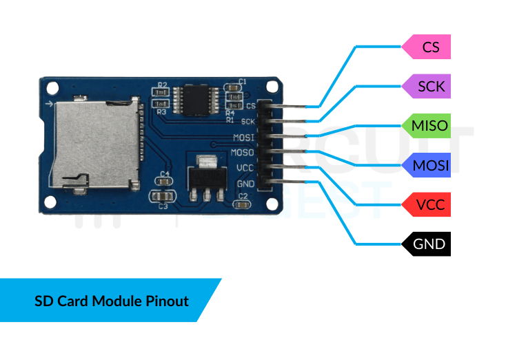
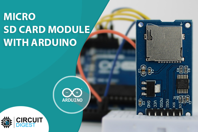
The image below explains the pins of the SD card module.
Usually, an SD card module includes the following pins:
Connects to 3.3V on the Pico.
Common reference ground.
SD → Pico data line.
Pico → SD data line.
Clock signal from Pico.
Select the SD module on the SPI bus.
Some SD card modules label the data pins as DI (Data In) and DO (Data Out). DI actually stands for MOSI, while DO stands for MISO.
SD Card Module Hardware Components Explained
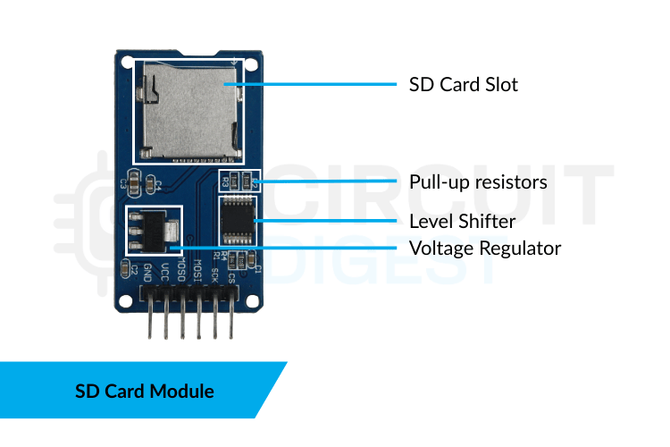
Understanding the internal components of your SD card module helps troubleshoot issues and ensures proper operation when interfacing the SD card module with Raspberry Pi Pico. The major components in the SD card module are explained below:
Key hardware elements on the SD card module include:
AMS1117-3.3 Regulator Steps down 5V to 3.3V, ensuring safe SD card operation.
Level Shifters (On some modules) Transistor/resistor networks that convert 5V logic to 3.3V.
Pull-up Resistors Maintain correct logic states on SPI lines.
MicroSD Socket Accepts standard microSD cards.
The list of components required to interface the SD card module is listed in the table below.
RP2040-based microcontroller with SPI0 on pins GP16-GP19
Must include 3.3V regulator and SPI interface
For prototyping connections
Male-to-female or male-to-male depending on module
Micro-USB for power and programming
Circuit Diagram: Interfacing SD Card Module with Raspberry Pi Pico Pin Configuration
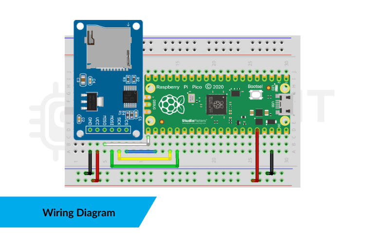
The following wiring diagram shows the complete Raspberry Pi Pico SD card Arduino connection scheme using the Pico's default SPI0 interface. To interface the SD card with the Raspberry Pi Pico, refer to the following image,
Raspberry Pi Pico SD Card Module SPI0 Wiring Configuration
The pinout for connecting your Raspberry Pi Pico SD card module is explained below:
Safe power for SD module
This wiring matches exactly with the Pico’s default SPI0 interface used by the Arduino-Pico core, so the SD library knows which pins to use for your Raspberry Pi Pico SD card reader. Once the Pico is properly connected, it communicates with the SD module through its SPI0 bus. The Arduino SD.h library takes care of the following things following operations for your Raspberry Pi Pico SD card reader:
Sending and receiving data over the SPI bus
Creating and deleting files
Managing the memory used for reading and writing
Handling folders and files on a FAT32-formatted SD card
This project includes a menu system that works with the Serial Monitor, letting users start SD card tasks on their Raspberry Pi Pico SD card reader interactively.
Preparing Your SD Card for Raspberry Pi Pico Interface
Proper SD card preparation is critical for successful interfacing of the SD card module with Raspberry Pi Pico. Follow these steps to ensure your Raspberry Pi Pico SD card reader works correctly:
Steps to Prepare the Card for Raspberry Pi Pico SD Card Module
Remove all existing partitions using Disk Management.
Create one primary partition, and make sure the card uses MBR, not GPT.
Format the card to FAT32.
If the SD card is larger than 8GB, create a partition of only 4GB or 8GB and leave the excess space unallocated.
Windows won’t format cards larger than 32GB to FAT32 by default.
For SDXC cards, use Rufus or GUIFormat to format them correctly.
Insert the card into the SD module.
If the card isn’t formatted as FAT32 or if it uses a GPT partition table, your Raspberry Pi Pico SD card reader will not initialize it properly, and the serial monitor shows that “ The SD card is not initialized ”.
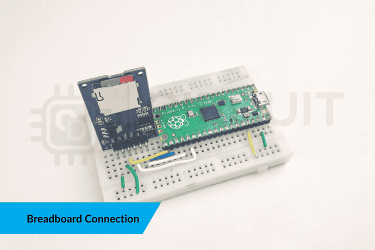
The following images show the breadboard interface of the SD card module with the Raspberry Pi Pico microcontroller.
\"SD init FAILED\" error
Reformat to FAT32 using Rufus
Convert to MBR partition table
Only first partition accessible
Use single primary partition
Ensure card clicks into socket fully
Raspberry Pi Pico Arduino Code for SD Card Module Interface
Proper SD card preparation is critical for successful interfacing of the SD card module with Raspberry Pi Pico. The following Raspberry Pi Pico SD card Arduino code creates an interactive menu system for file operations via the Serial Monitor. The firmware part consists of two libraries, one for SPI communication and another for SD card interfacing.
Here, SPI.h and SD.h give the Pico access to the SPI bus and SD card functions. The CSPIN value tells the library which GPIO pin is used as the Chip Select line, and demo.txt is the file we will create, write to, read from, and delete. Next, the Pico begins Serial communication and tries to initialise the SD card:
This sets the baud rate and mounts the SD card. If the card is not formatted correctly or the wiring is wrong, the SD initialisation will fail here. The main loop waits for the user to enter a number in the Serial Monitor:
When the user types 1, 2, 3, or 4, the switch statement decides which SD-card action to perform. Creating a file is simple:
Opening a file in write mode automatically creates it if it doesn’t already exist. A default message is added, and the file is closed properly. Writing custom text works in the same way, but this time the text comes from the user:
This appends whatever the user typed into the Serial Monitor. Reading a file is just opening it in read mode and printing each character:
This streams the file contents back to the Serial Monitor so the user can see exactly what was saved. Finally, deleting the file is done with a single command:
This removes demo.txt from the SD card and resets the project back to the initial state.
Working Demonstration: Raspberry Pi Pico SD Card Module
When the system powers up with the Raspberry Pi Pico SD card properly connected:
The Pico displays the SD menu options on the Serial Monitor.
The user selects 1, 2, 3, or 4 to perform a specific file operation on the Raspberry Pi Pico SD card reader.
The Pico carries out the action immediately on the SD card, and the Serial Monitor shows the result in real time.
This demo clearly walks through how the Pico handles file operations on a small storage module, a useful concept for IoT data logging, saving device settings, and storing information offline.
Troubleshooting Guide: Common Issues with Raspberry Pi Pico SD Card Module
Problem 1: \"SD init FAILED\" Error Message on Raspberry Pi Pico SD Card Reader.
In this project, I'm utilising the same concept with the Raspberry Pi Pico SD card Arduino integration and enhancing the experience to make it more interactive. Since this is about interfacing the SD card module with the Raspberry Pi Pico, I’ve set up the Pico to respond directly to whatever the user types in the Serial Monitor. Want to create a file? Press a key. Want to enter your own text? Just type it in. Need to read from or delete a file? Simply give a command, and the Raspberry Pi Pico SD card module setup handles it immediately. This gives you a clear, real-time view of what's happening behind the scenes as the Pico communicates over SPI, initialises the SD card, and performs FAT32 file operations. By the time you try all the menu options, you’ll fully understand how to interface an SD card to Pico and how embedded systems handle external storage. And once you master these fundamentals of how to interface an SD card to Pico, you'll be well-prepared for more advanced projects, such as the non-contact wall-mount infrared thermometer with SD card logging, where long-term, reliable data storage is the foundation of the entire system.
Understanding the SD Card Module
SD Card Module Pin Configuration
Hardware Components Explained
└ Components Required
└ Common Formatting Mistakes to Avoid
Working Demonstration
Troubleshooting Guide
Understanding the Raspberry Pi Pico SD Card Module
The SD card module is a simple and reliable way to add external storage to your projects. When you interface an SD card to the pico, the Raspberry Pi Pico SD card module handles voltage regulation and level shifting automatically, protecting both the microcontroller and the microSD card. It uses the SPI interface, which makes it easy for microcontrollers like the Raspberry Pi Pico to send and receive data from a microSD card. Most modules come with a built-in 3.3V regulator and basic level shifting, so the SD card stays protected while you read and write files. For beginners, the Raspberry Pi Pico SD card reader is one of the easiest ways to start working with real data storage, like logging values, saving settings, or keeping simple text files, all with just a few wires. This makes the Raspberry Pi Pico SD card Arduino integration straightforward and beginner-friendly for data logging, configuration storage, and embedded file systems.
SD Card Module Pin Configuration for Raspberry Pi Pico
The image below explains the pins of the SD card module.
Usually, an SD card module includes the following pins:
Connects to 3.3V on the Pico.
Common reference ground.
SD → Pico data line.
Pico → SD data line.
Clock signal from Pico.
Select the SD module on the SPI bus.
Some SD card modules label the data pins as DI (Data In) and DO (Data Out). DI actually stands for MOSI, while DO stands for MISO.
SD Card Module Hardware Components Explained
Understanding the internal components of your SD card module helps troubleshoot issues and ensures proper operation when interfacing the SD card module with Raspberry Pi Pico. The major components in the SD card module are explained below:
Key hardware elements on the SD card module include:
AMS1117-3.3 Regulator Steps down 5V to 3.3V, ensuring safe SD card operation.
Level Shifters (On some modules) Transistor/resistor networks that convert 5V logic to 3.3V.
Pull-up Resistors Maintain correct logic states on SPI lines.
MicroSD Socket Accepts standard microSD cards.
The list of components required to interface the SD card module is listed in the table below.
RP2040-based microcontroller with SPI0 on pins GP16-GP19
Must include 3.3V regulator and SPI interface
For prototyping connections
Male-to-female or male-to-male depending on module
Micro-USB for power and programming
Circuit Diagram: Interfacing SD Card Module with Raspberry Pi Pico Pin Configuration
The following wiring diagram shows the complete Raspberry Pi Pico SD card Arduino connection scheme using the Pico's default SPI0 interface. To interface the SD card with the Raspberry Pi Pico, refer to the following image,
Raspberry Pi Pico SD Card Module SPI0 Wiring Configuration
The pinout for connecting your Raspberry Pi Pico SD card module is explained below:
Safe power for SD module
This wiring matches exactly with the Pico’s default SPI0 interface used by the Arduino-Pico core, so the SD library knows which pins to use for your Raspberry Pi Pico SD card reader. Once the Pico is properly connected, it communicates with the SD module through its SPI0 bus. The Arduino SD.h library takes care of the following things following operations for your Raspberry Pi Pico SD card reader:
Sending and receiving data over the SPI bus
Creating and deleting files
Managing the memory used for reading and writing
Handling folders and files on a FAT32-formatted SD card
This project includes a menu system that works with the Serial Monitor, letting users start SD card tasks on their Raspberry Pi Pico SD card reader interactively.
Preparing Your SD Card for Raspberry Pi Pico Interface
Proper SD card preparation is critical for successful interfacing of the SD card module with Raspberry Pi Pico. Follow these steps to ensure your Raspberry Pi Pico SD card reader works correctly:
Steps to Prepare the Card for Raspberry Pi Pico SD Card Module
Remove all existing partitions using Disk Management.
Create one primary partition, and make sure the card uses MBR, not GPT.
Format the card to FAT32.
If the SD card is larger than 8GB, create a partition of only 4GB or 8GB and leave the excess space unallocated.
Windows won’t format cards larger than 32GB to FAT32 by default.
For SDXC cards, use Rufus or GUIFormat to format them correctly.
Insert the card into the SD module.
If the card isn’t formatted as FAT32 or if it uses a GPT partition table, your Raspberry Pi Pico SD card reader will not initialize it properly, and the serial monitor shows that “ The SD card is not initialized ”.
The following images show the breadboard interface of the SD card module with the Raspberry Pi Pico microcontroller.
\"SD init FAILED\" error
Reformat to FAT32 using Rufus
Convert to MBR partition table
Only first partition accessible
Use single primary partition
Ensure card clicks into socket fully
Raspberry Pi Pico Arduino Code for SD Card Module Interface
Proper SD card preparation is critical for successful interfacing of the SD card module with Raspberry Pi Pico. The following Raspberry Pi Pico SD card Arduino code creates an interactive menu system for file operations via the Serial Monitor. The firmware part consists of two libraries, one for SPI communication and another for SD card interfacing.
Here, SPI.h and SD.h give the Pico access to the SPI bus and SD card functions. The CSPIN value tells the library which GPIO pin is used as the Chip Select line, and demo.txt is the file we will create, write to, read from, and delete. Next, the Pico begins Serial communication and tries to initialise the SD card:
This sets the baud rate and mounts the SD card. If the card is not formatted correctly or the wiring is wrong, the SD initialisation will fail here. The main loop waits for the user to enter a number in the Serial Monitor:
When the user types 1, 2, 3, or 4, the switch statement decides which SD-card action to perform. Creating a file is simple:
Opening a file in write mode automatically creates it if it doesn’t already exist. A default message is added, and the file is closed properly. Writing custom text works in the same way, but this time the text comes from the user:
This appends whatever the user typed into the Serial Monitor. Reading a file is just opening it in read mode and printing each character:
This streams the file contents back to the Serial Monitor so the user can see exactly what was saved. Finally, deleting the file is done with a single command:
This removes demo.txt from the SD card and resets the project back to the initial state.
Working Demonstration: Raspberry Pi Pico SD Card Module
When the system powers up with the Raspberry Pi Pico SD card properly connected:
The Pico displays the SD menu options on the Serial Monitor.
The user selects 1, 2, 3, or 4 to perform a specific file operation on the Raspberry Pi Pico SD card reader.
The Pico carries out the action immediately on the SD card, and the Serial Monitor shows the result in real time.
This demo clearly walks through how the Pico handles file operations on a small storage module, a useful concept for IoT data logging, saving device settings, and storing information offline.
Troubleshooting Guide: Common Issues with Raspberry Pi Pico SD Card Module
Problem 1: \"SD init FAILED\" Error Message on Raspberry Pi Pico SD Card Reader.
Technologies used
Hardware components
- AMS1117-3.3 RegulatorSteps down 5V to 3.3V
- ensuring safe SD card operation.
- Level Shifters (On some modules)Transistor/resistor networks that convert 5V logic to 3.3V.
- Pull-up ResistorsMaintain correct logic states on SPI lines.
- MicroSD SocketAccepts standard microSD cards.
Project demo video
What you get
- Working project / hardware kit, tested before delivery
- Complete source code with explanation
- Project demo and guidance for your viva
- Project report, PPT and IEEE paper support (on request)
Delivery & Payment
Delivery takes a minimum of two weeks from the date your inquiry is confirmed.
Payment is in two parts:
• 50% advance to start the project
• Remaining 50% before delivery
Note:
• Documentation and PPT are not included by default
• If you need documentation/PPT, it can be arranged for extra time and cost
We'll confirm the exact timeline and cost with you after reviewing your requirements.
Related Embedded projects

Embedded
ESP32 Fingerprint Attendance System with Live Web Dashboard
Build a biometric attendance system using ESP32 with AS608 fingerprint sensor that logs attendance with timestamp to web dashboard and Googl...
View project
Embedded
Mars Rover Robot Replica using ESP32 CAM and Arduino
Build a Mars Rover robot replica using ESP32-CAM and Arduino with a rocker-bogie suspension system, live video streaming, and smartphone app...
View project
Embedded
ESP32 CAN Bus Tutorial Interfacing MCP2515 with ESP32
Learn CAN bus communication with ESP32 and MCP2515 CAN controller to send and receive data in automotive and industrial applications.
View project
Embedded
ESP32 MP3 Music Player with SD Card and I2S Amplifier
Build a standalone ESP32 MP3 music player that reads audio from SD card and outputs high-quality audio via I2S DAC amplifier with web contro...
View project