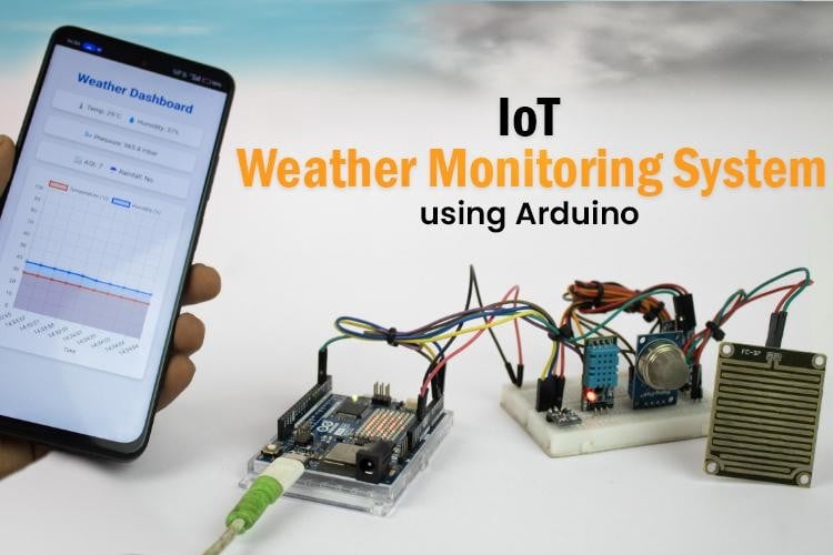


How to Build an IoT-based Weather Monitoring System Using Arduino?
Learn how to build a WiFi-enabled Arduino Weather Monitoring System that reads temperature, humidity, pressure, air quality, and more using sensors like DHT11, BMP180, and MQ135. This hands-on project teaches you sensor integration, real-time data handling, and creating a dynamic local web page for monitoring environmental conditions.
- Suitable forM.Tech Embedded students
- Build time3-4 weeks
- LevelBeginner
- Available atAjvika Labs, Kakinada
About this project
No need to stress about complicated cloud setups or costly subscription plans. This DIY IoT Weather Station project only requires a few environmental sensors and the versatile Arduino UNO R4 WiFi board. It blends IoT, web development, and embedded programming, making it an ideal IoT project for beginners, students, and tech enthusiasts interested in smart weather systems, Arduino projects, and real-time data monitoring.
If you are new to Arduino UNO R4, then I strongly recommend that you go through this “ Getting Started with Arduino UNO R4 & Arduino IoT Cloud ” tutorial before proceeding.
What is an IoT-Based Weather Monitoring System?
Hardware Setup and Connections
Arduino Code Explanation
Flash Code into Arduino
Working Demonstration
GitHub Repository with Code and Circuit
Similar IoT-Based Weather Monitoring Projects
What is an IoT-Based Weather Monitoring System?
An IoT-Based Weather Monitoring System uses sensors to collect real-time environmental data like temperature, humidity, and air pressure. It transmits the data to the cloud using IoT protocols such as Wi-Fi or LoRa. Users can access this information remotely via the web or mobile apps. This system helps in accurate forecasting, environmental research, and smart agriculture.
This Arduino Weather Monitoring System Project is very helpful in getting to know about your surrounding weather status from indoors. What makes this project different from others is that it gives you the advantage of fully customizing the local webpage user interface based on your creativity, whereas you can’t get this level of flexibility from the cloud platforms.
The image below shows the weather monitoring system using an IoT block diagram. Let's understand how it works by splitting it into three sections
Gathering The Data From The Environment
This system uses a wide range of environmental sensors to capture the weather key parameters like temperature, humidity level, Atmospheric pressure, AQI Index, and Rainfall status continuously and send that data to Arduino through serial communication protocols as well as Normal Analog and Digital signals.
Serving The Locally Accessible Webpage
After getting the weather data from the environmental sensors, Arduino creates the local webpage that displays the sensor data by turning itself into a mini local web server. This means you can know weather data from a phone, tablet, or computer by simply connecting to the same network where the Arduino is connected.
Dynamically Updating The Webpage for Live Updates
Arduino-served Webpage keeps on refreshing the data dynamically, so you’ll always see the latest weather info. Whether the temperature rises, the humidity changes, or the Rain is falling, you will see instantly on your device. No need to manually refresh the webpage every time.
Here are the components needed to build an Arduino Weather Monitoring System. Let’s see what things we need to build it.
BMP180 Barometric Pressure Sensor
BMP180 Barometric Pressure Sensor
DHT11 Temperature & Humidity Sensor
DHT11 Temperature & Humidity Sensor
MQ135 Air Monitoring Sensor
MQ135 Air Monitoring Sensor
Rain Sensor with Sensor Module
Rain Sensor with Sensor Module
As you can see from the above components list, we will be using 4 different sensors to read various parameters like temperature, humidity, pressure, air quality, rain status, etc from the atmosphere. If you are a complete beginner with these sensors, check out the BMP180 tutorial, DHT11 Tutorial, MQ135 Tutorial, and Rain Sensor tutorial to understand how these sensors work and how you can use them with Arduino.
Circuit Diagram for Arduino-Based Weather Monitoring System
In the above image, you can find the circuit diagram of our Weather Monitoring System using Arduino. This circuit diagram helps turn our scattered electronic components found on the workbench into a functional Mini Weather Station.
As you can see, I am using a wide variety of sensors here for measuring each weather parameter, like
BMP180 Sensor - used for measuring the Atmospheric pressure. If the pressure is High means “Clear, sunny weather!” and if the pressure is low, it means “Rainy or stormy weather!”
BMP180 Sensor - used for measuring the Atmospheric pressure. If the pressure is High means “Clear, sunny weather!” and if the pressure is low, it means “Rainy or stormy weather!”
DHT11 Sensor - used for measuring Temperature and Humidity. Here, temperature tells “How warm or cool the Air is” and humidity tells “How much water vapour is in the Air”.
DHT11 Sensor - used for measuring Temperature and Humidity. Here, temperature tells “How warm or cool the Air is” and humidity tells “How much water vapour is in the Air”.
MQ135 Sensor - used for measuring the Pollutants present in the Air. Here, monitoring the AQI(pollutant level) is important for health reasons, especially if we have asthma or lung allergies. (Note, it is not accurate, but might work well in indoor/outdoor environments)
MQ135 Sensor - used for measuring the Pollutants present in the Air. Here, monitoring the AQI(pollutant level) is important for health reasons, especially if we have asthma or lung allergies. (Note, it is not accurate, but might work well in indoor/outdoor environments)
Rain sensor - used for detecting whether it’s currently raining or not.
Rain sensor - used for detecting whether it’s currently raining or not.
The Arduino UNO R4 WiFi collects all of this sensor data and makes the live data reflected on the Local Webpage instantly.
Hardware Pinout of IoT Weather Monitoring System
To make the hardware connection easy to understand, we have given a connection mapping below that explains the connection between your Arduino board and the various environmental sensors.
Hardware Setup of Weather Monitoring System using Arduino
Here is the complete hardware that was built from using the above circuit diagram as a blueprint
For power supply, you can either power it through the 12V DC jack port or through the USB port.
Arduino Code for IoT-based Weather Monitoring System
Before jumping into the code explanation, I will give you a short overview of this code. First of all, this code, ensures our Arduino UNO R4 WiFi is connected to our Local Access point. After that, it starts to serve the dynamic webpage by acting as a local web server.
At the same time, it continuously retrieves data from the sensor every second and makes that data reflect on that dynamic webpage with a graphical chart format. It also utilizes the built-in 12x8 LED matrix for displaying the connection status. It ensures Arduino automatically connects to the Hotspot whenever it gets disconnected.
I hope you get a clear overview. Let’s move on to a step-by-step code explanation.
1. Adafruit_BMP085.h && Adafruit_Sensor.h
- It helps in interfacing with the BMP180 using simpler I2C APIs as well to parse the Humidity data.
It is used for establishing a connection with the DHT11 sensor through its serial communication protocol with ease.
3. Arduino_LED_Matrix.h
Arduino UNO R4 built-in 8x12 LED matrix can be easily customizable using its provided prebuilt routines.
We know Arduino UNO R4 supports WiFi features, where this library comes in handy for easy WiFi setup and configuration.
Note “ Arduino_LED_Matrix.h ” and “ WiFiS3.h ” come along with the board support package of Arduino UNO R4 WiFi. So, we don’t need to install it separately.
You can easily get this library by clicking the appropriate header file name.
After downloading the ZIP file from the GitHub repo, you can install it either through the Arduino IDE, by going to Sketch -> Include Library -> Add ZIP Library and selecting the downloaded ZIP file, or by simply extracting the ZIP file into the Arduino library folder.
Here, I used macros to hold the pin data of the Rain sensor, DHT11 sensor, and MQ135 sensor, where the sensor is going to connect to the appropriate pin of the Arduino.
This step is about creating objects for the sensor, WiFi, and LED matrix to easily use the prebuilt APIs.
Here, I am creating a new object for the DHT11 sensor, and the BMP180 sensor to initialize it properly by passing its pin details and the type of sensor used.
Whereas the creation of a server() object to make use of the WiFi module’s Web Server capability and a matrix object to control the built-in LED matrix with ease by utilizing its class specific API’s.
Here, these two array variables, wifi_connected[] && no_wifi[] hold the hexadecimal code, which is vital for bringing up the wifi connected symbol and wifi disconnected symbol on Arduino UNO R4’s builtin 12x8 LED Matrix.
ssid[] and pass[] character array is used to hold your WiFi Router password. So that your Arduino UNO R4 can connect to this local network. Don’t forget to replace it with your Wifi router credentials.
These variables are used to hold the weather parameter info like temperature, humidity, pressure, AQI, and rainfall status, which was obtained from its respective sensors.
Here, these two variables act as status variables, where “lastSensorUpdate” keeps a record of the last time the weather data was fetched from the sensor, and “lastWiFiCheck” tracks the last time the Wi-Fi status was checked.
wifi_connect() Function establishes the initial connection to the specified WiFi network.
The wifi_connect() function is used for making a wifi connection with the authorized hotspot using its wifi credentials details.
While trying to connect to the hotspot, it brings a wifi connection animation on the built-in 12x8 LED matrix, to indicate the board is trying to connect to the internet. Later, it brings out a stable WiFi symbol after successful connection with the Hotspot.
wifi_reconnect() Function handles automatic reconnection to the network if the WiFi connection is lost.
This wifi_reconnect() gets used when we need to re-establish the connection between the Arduino and the Hotspot after getting lost.
Whenever the connection gets lost, it brings out the “ No Internet ” symbol on the LED matrix and tries to connect again by calling out the wifi_connect() function.
read_sensor_data() function retrieves real-time data from the connected sensors.
Here, the read_sensor_data() function is used to fetch the weather parameter data from the respective sensors by utilizing the sensor-specific APIs. After collecting data, it does unit conversions like converting pressure from Pa to mbar & raw air sensor value to PPM and makes it to store in respective global variables.
send_json_data() function sends real-time JSON data to the user's web browser.
The send_json_data() function is responsible for fetching the weather data from the global variables and sending weather data from the Arduino to a connected client(Browser) in JSON format over WiFi.
The response contains the weather data in a structured format, making it easy for the client to parse and display.
The function serves the dynamic web page directly to the user's web browser.
Technologies used
Hardware components
- Arduino UNO R4 WiFi
- BMP180 Barometric Pressure Sensor
- DHT11 Temperature & Humidity Sensor
- MQ135 Air Monitoring Sensor
- Rain Sensor with Sensor Module
- Breadboard
- Connecting Wires
Software & tools
- Arduino IDE
Project demo video
What you get
- Working project / hardware kit, tested before delivery
- Complete source code with explanation
- Project demo and guidance for your viva
- Project report, PPT and IEEE paper support (on request)
Related Embedded projects

ESP32 Fingerprint Attendance System with Live Web Dashboard
Build a biometric attendance system using ESP32 with AS608 fingerprint sensor that logs attendance with timestamp to web dashboard and Googl...
View project
Mars Rover Robot Replica using ESP32 CAM and Arduino
Build a Mars Rover robot replica using ESP32-CAM and Arduino with a rocker-bogie suspension system, live video streaming, and smartphone app...
View project
ESP32 CAN Bus Tutorial Interfacing MCP2515 with ESP32
Learn CAN bus communication with ESP32 and MCP2515 CAN controller to send and receive data in automotive and industrial applications.
View project
ESP32 MP3 Music Player with SD Card and I2S Amplifier
Build a standalone ESP32 MP3 music player that reads audio from SD card and outputs high-quality audio via I2S DAC amplifier with web contro...
View project