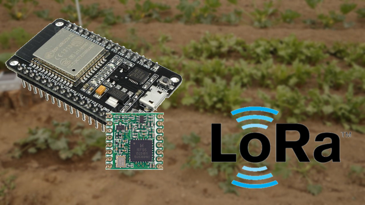
ESP32 with LoRa using Arduino IDE – Getting Started
Learn LoRa basics and how it can be used with the ESP32 for IoT projects using the Arduino IDE. You'll also create a LoRa Sender and LoRa Receiver with RFM95
- Suitable forB.Tech/Diploma IoT/ESP32 students
- Build time1-2 weeks
- LevelBeginner
- Available atAjvika Labs, Kakinada
About this project
In this tutorial we’ll explore the basic principles of LoRa, and how it can be used with the ESP32 for IoT projects using the Arduino IDE. To get you started, we’ll also show you how to create a simple LoRa Sender and LoRa Receiver with the RFM95 transceiver module.
Introducing LoRa
What is LoRa?
LoRa is a wireless data communication technology that uses a radio modulation technique that can be generated by Semtech LoRa transceiver chips.
This modulation technique allows long range communication of small amounts of data (which means a low bandwidth), high immunity to interference, while minimizing power consumption. So, it allows long distance communication with low power requirements.
LoRa Frequencies
LoRa uses unlicensed frequencies that are available worldwide. These are the most widely used frequencies:
868 MHz for Europe
915 MHz for North America
433 MHz band for Asia
Because these bands are unlicensed, anyone can freely use them without paying or having to get a license. Check the
frequencies used in your country
LoRa Applications
LoRa long range and low power features, makes it perfect for battery-operated sensors and low-power applications in:
Internet of Things (IoT)
Smart home
Machine-to-machine communication
And much more…
So, LoRa is a good choice for sensor nodes running on a coil cell or solar powered, that transmit small amounts of data.
Keep in mind that LoRa is not suitable for projects that:
Require high data-rate transmission;
Need very frequent transmissions;
Or are in highly populated networks.
LoRa Topologies
You can use LoRa in:
Point to point communication
Or build a LoRa network (using LoRaWAN for example)
Point to Point Communication
In point to point communication, two LoRa enabled devices talk with each other using RF signals.
For example, this is useful to exchange data between two ESP32 boards equipped with LoRa transceiver chips that are relatively far from each other or in environments without Wi-Fi coverage.
Unlike Wi-Fi or Bluetooth that only support short distance communication, two LoRa devices with a proper antenna can exchange data over a long distance.
You can easily configure your ESP32 with a LoRa chip to transmit and receive data reliably at more than 200 meters distance (you can get better results depending on your enviroment and LoRa settings). There are also other LoRa solutions that easily have a range of more than 30Km.
LoRaWAN
You can also build a LoRa network using LoRaWAN.
The LoRaWAN protocol is a Low Power Wide Area Network (LPWAN) specification derived from LoRa technology standardized by the LoRa Alliance. We won’t explore LoRaWAN in this tutorial, but for more information you can check the
LoRa Alliance
and
The Things Network
websites.
How can LoRa be useful in your home automation projects?
Let’s take a look at a practical application.
Imagine that you want to measure the moisture in your field. Although, it is not far from your house, it probably doesn’t have Wi-Fi coverage. So, you can build a sensor node with an ESP32 and a moisture sensor, that sends the moisture readings once or twice a day to another ESP32 using LoRa.
The later ESP32 has access to Wi-Fi, and it can run a web server that displays the moisture readings.
This is just an example that illustrates how you can use the LoRa technology in your ESP32 projects.
Note:
we teach how to build this project on our “
Learn ESP32 with Arduino IDE
” course. It is Project 4 on the Table of Contents:
LoRa Long Range Sensor Monitoring – Reporting Sensor Readings from Outside: Soil Moisture and Temperature
Check the
course page
for more details.
ESP32 with LoRa
In this section we’ll show you how to get started with LoRa with your ESP32 using Arduino IDE. As an example, we’ll build a simple LoRa Sender and a LoRa Receiver.
The LoRa Sender will be sending a “hello” message followed by a counter for testing purposes. This message can be easily replaced with useful data like sensor readings or notifications.
To follow this part you need the following components:
2x ESP32 DOIT DEVKIT V1 Board
2x LoRa Transceiver modules (RFM95)
RFM95 LoRa breakout board (optional)
Jumper wires
Breadboard
or
stripboard
Alternative:
2x TTGO LoRa32 SX1276 OLED
Instead of using an ESP32 and a separated LoRa transceiver module, there are ESP32 development boards with a LoRa chip and an OLED built-in, which makes wiring much simpler. If you have one of those boards, you can follow:
TTGO LoRa32 SX1276 OLED Board: Getting Started with Arduino IDE
You can use the preceding links or go directly to
MakerAdvisor.com/tools
to find all the parts for your projects at the best price!
Preparing the Arduino IDE
There’s an add-on for the Arduino IDE that allows you to program the ESP32 using the Arduino IDE and its programming language. Follow one of the next tutorials to prepare your Arduino IDE to work with the ESP32, if you haven’t already.
Windows
instructions – ESP32 Board in Arduino IDE
Mac and Linux
instructions – ESP32 Board in Arduino IDE
Installing the LoRa Library
There are several libraries available to easily send and receive LoRa packets with the ESP32. In this example we’ll be using the
arduino-LoRa library by sandeep mistry
Open your Arduino IDE, and go to
Sketch
>
Include Library
>
Manage Libraries
and search for “
LoRa
“. Select the LoRa library highlighted in the figure below, and install it.
Getting LoRa Tranceiver Modules
To send and receive LoRa messages with the ESP32 we’ll be using the
RFM95 transceiver module
. All LoRa modules are transceivers, which means they can send and receive information. You’ll need 2 of them.
You can also use other compatible modules like Semtech SX1276/77/78/79 based boards including: RFM96W, RFM98W, etc…
Alternatively, there are ESP32 boards with LoRa and OLED display built-in like the
ESP32 Heltec Wifi Module
, or the
TTGO LoRa32 board
Before getting your LoRa transceiver module, make sure you check the correct frequency for your location. You can visit the following web page to learn more about
RF signals and regulations according to each country
. For example, in Portugal we can use a frequency between 863 and 870 MHz or we can use 433MHz. For this project, we’ll be using an RFM95 that operates at 868 MHz.
Preparing the RFM95 Transceiver Module
If you have an ESP32 development board with LoRa built-in, you can skip this step.
The RFM95 transceiver isn’t breadboard friendly. A common row of 2.54mm header pins won’t fit on the transceiver pins. The spaces between the connections are shorter than usual.
There are a few options that you can use to access the transceiver pins.
You may solder some wires directly to the transceiver;
Break header pins and solder each one separately;
Or you can buy a breakout board that makes the pins breadboard friendly.
We’ve soldered a header to the module as shown in the figure below.
This way you can access the module’s pins with regular jumper wires, or even put some header pins to connect them directly to a stripboard or breadboard.
Antenna
The RFM95 transceiver chip requires an external antenna connected to the ANA pin.
You can connect a “real” antenna, or you can make one yourself by using a conductive wire as shown in the figure below. Some breakout boards come with a special connector to add a proper antenna.
The wire length depends on the frequency:
868 MHz: 86,3 mm (3.4 inch)
915 MHz: 81,9 mm (3.22 inch)
433 MHz: 173,1 mm (6.8 inch)
For our module we need to use a 86,3 mm wire soldered directly to the transceiver’s ANA pin. Note that using a proper antenna will extend the communication range.
Important:
you MUST attach an antenna to the module.
Wiring the RFM95 LoRa Transceiver Module
The RFM95 LoRa transceiver module communicates with the ESP32 using SPI communication protocol. So, we’ll use the ESP32 default SPI pins
Introducing LoRa
What is LoRa?
LoRa is a wireless data communication technology that uses a radio modulation technique that can be generated by Semtech LoRa transceiver chips.
This modulation technique allows long range communication of small amounts of data (which means a low bandwidth), high immunity to interference, while minimizing power consumption. So, it allows long distance communication with low power requirements.
LoRa Frequencies
LoRa uses unlicensed frequencies that are available worldwide. These are the most widely used frequencies:
868 MHz for Europe
915 MHz for North America
433 MHz band for Asia
Because these bands are unlicensed, anyone can freely use them without paying or having to get a license. Check the
frequencies used in your country
LoRa Applications
LoRa long range and low power features, makes it perfect for battery-operated sensors and low-power applications in:
Internet of Things (IoT)
Smart home
Machine-to-machine communication
And much more…
So, LoRa is a good choice for sensor nodes running on a coil cell or solar powered, that transmit small amounts of data.
Keep in mind that LoRa is not suitable for projects that:
Require high data-rate transmission;
Need very frequent transmissions;
Or are in highly populated networks.
LoRa Topologies
You can use LoRa in:
Point to point communication
Or build a LoRa network (using LoRaWAN for example)
Point to Point Communication
In point to point communication, two LoRa enabled devices talk with each other using RF signals.
For example, this is useful to exchange data between two ESP32 boards equipped with LoRa transceiver chips that are relatively far from each other or in environments without Wi-Fi coverage.
Unlike Wi-Fi or Bluetooth that only support short distance communication, two LoRa devices with a proper antenna can exchange data over a long distance.
You can easily configure your ESP32 with a LoRa chip to transmit and receive data reliably at more than 200 meters distance (you can get better results depending on your enviroment and LoRa settings). There are also other LoRa solutions that easily have a range of more than 30Km.
LoRaWAN
You can also build a LoRa network using LoRaWAN.
The LoRaWAN protocol is a Low Power Wide Area Network (LPWAN) specification derived from LoRa technology standardized by the LoRa Alliance. We won’t explore LoRaWAN in this tutorial, but for more information you can check the
LoRa Alliance
and
The Things Network
websites.
How can LoRa be useful in your home automation projects?
Let’s take a look at a practical application.
Imagine that you want to measure the moisture in your field. Although, it is not far from your house, it probably doesn’t have Wi-Fi coverage. So, you can build a sensor node with an ESP32 and a moisture sensor, that sends the moisture readings once or twice a day to another ESP32 using LoRa.
The later ESP32 has access to Wi-Fi, and it can run a web server that displays the moisture readings.
This is just an example that illustrates how you can use the LoRa technology in your ESP32 projects.
Note:
we teach how to build this project on our “
Learn ESP32 with Arduino IDE
” course. It is Project 4 on the Table of Contents:
LoRa Long Range Sensor Monitoring – Reporting Sensor Readings from Outside: Soil Moisture and Temperature
Check the
course page
for more details.
ESP32 with LoRa
In this section we’ll show you how to get started with LoRa with your ESP32 using Arduino IDE. As an example, we’ll build a simple LoRa Sender and a LoRa Receiver.
The LoRa Sender will be sending a “hello” message followed by a counter for testing purposes. This message can be easily replaced with useful data like sensor readings or notifications.
To follow this part you need the following components:
2x ESP32 DOIT DEVKIT V1 Board
2x LoRa Transceiver modules (RFM95)
RFM95 LoRa breakout board (optional)
Jumper wires
Breadboard
or
stripboard
Alternative:
2x TTGO LoRa32 SX1276 OLED
Instead of using an ESP32 and a separated LoRa transceiver module, there are ESP32 development boards with a LoRa chip and an OLED built-in, which makes wiring much simpler. If you have one of those boards, you can follow:
TTGO LoRa32 SX1276 OLED Board: Getting Started with Arduino IDE
You can use the preceding links or go directly to
MakerAdvisor.com/tools
to find all the parts for your projects at the best price!
Preparing the Arduino IDE
There’s an add-on for the Arduino IDE that allows you to program the ESP32 using the Arduino IDE and its programming language. Follow one of the next tutorials to prepare your Arduino IDE to work with the ESP32, if you haven’t already.
Windows
instructions – ESP32 Board in Arduino IDE
Mac and Linux
instructions – ESP32 Board in Arduino IDE
Installing the LoRa Library
There are several libraries available to easily send and receive LoRa packets with the ESP32. In this example we’ll be using the
arduino-LoRa library by sandeep mistry
Open your Arduino IDE, and go to
Sketch
>
Include Library
>
Manage Libraries
and search for “
LoRa
“. Select the LoRa library highlighted in the figure below, and install it.
Getting LoRa Tranceiver Modules
To send and receive LoRa messages with the ESP32 we’ll be using the
RFM95 transceiver module
. All LoRa modules are transceivers, which means they can send and receive information. You’ll need 2 of them.
You can also use other compatible modules like Semtech SX1276/77/78/79 based boards including: RFM96W, RFM98W, etc…
Alternatively, there are ESP32 boards with LoRa and OLED display built-in like the
ESP32 Heltec Wifi Module
, or the
TTGO LoRa32 board
Before getting your LoRa transceiver module, make sure you check the correct frequency for your location. You can visit the following web page to learn more about
RF signals and regulations according to each country
. For example, in Portugal we can use a frequency between 863 and 870 MHz or we can use 433MHz. For this project, we’ll be using an RFM95 that operates at 868 MHz.
Preparing the RFM95 Transceiver Module
If you have an ESP32 development board with LoRa built-in, you can skip this step.
The RFM95 transceiver isn’t breadboard friendly. A common row of 2.54mm header pins won’t fit on the transceiver pins. The spaces between the connections are shorter than usual.
There are a few options that you can use to access the transceiver pins.
You may solder some wires directly to the transceiver;
Break header pins and solder each one separately;
Or you can buy a breakout board that makes the pins breadboard friendly.
We’ve soldered a header to the module as shown in the figure below.
This way you can access the module’s pins with regular jumper wires, or even put some header pins to connect them directly to a stripboard or breadboard.
Antenna
The RFM95 transceiver chip requires an external antenna connected to the ANA pin.
You can connect a “real” antenna, or you can make one yourself by using a conductive wire as shown in the figure below. Some breakout boards come with a special connector to add a proper antenna.
The wire length depends on the frequency:
868 MHz: 86,3 mm (3.4 inch)
915 MHz: 81,9 mm (3.22 inch)
433 MHz: 173,1 mm (6.8 inch)
For our module we need to use a 86,3 mm wire soldered directly to the transceiver’s ANA pin. Note that using a proper antenna will extend the communication range.
Important:
you MUST attach an antenna to the module.
Wiring the RFM95 LoRa Transceiver Module
The RFM95 LoRa transceiver module communicates with the ESP32 using SPI communication protocol. So, we’ll use the ESP32 default SPI pins
Technologies used
Hardware components
- ESP32
- Arduino
- OLED
- SX1276
- Soil Moisture
Software & tools
- Arduino IDE
What you get
- Working project / hardware kit, tested before delivery
- Complete source code with explanation
- Project demo and guidance for your viva
- Project report, PPT and IEEE paper support (on request)
Delivery & Payment
Delivery takes a minimum of two weeks from the date your inquiry is confirmed.
Payment is in two parts:
• 50% advance to start the project
• Remaining 50% before delivery
Note:
• Documentation and PPT are not included by default
• If you need documentation/PPT, it can be arranged for extra time and cost
We'll confirm the exact timeline and cost with you after reviewing your requirements.
Related IoT/ESP32 projects

IoT/ESP32
ESP32 External Wake Up from Deep Sleep
This article shows how to put the ESP32 in deep sleep mode and wake it with an external wake up like a button press. We'll cover how to use...
View project
IoT/ESP32
ESP32: Upload Files to LittleFS using Arduino IDE
Upload files to the ESP32 Filesystem (LittleFS) by using a plugin for Arduino IDE (1.8.X). The plugin lets you use three different filesyste...
View project
IoT/ESP32
ESP32: Guide for MicroSD Card Module using Arduino IDE
Use a microSD card with the ESP32: you'll learn how to read and write files to the microSD card. To interface a microSD card with an ESP32 b...
View project
IoT/ESP32
ESP32 Save Data Permanently using Preferences Library
Save data permanently on the ESP32 flash memory using Preferences.h library. The data held in the flash memory persists across resets or pow...
View project