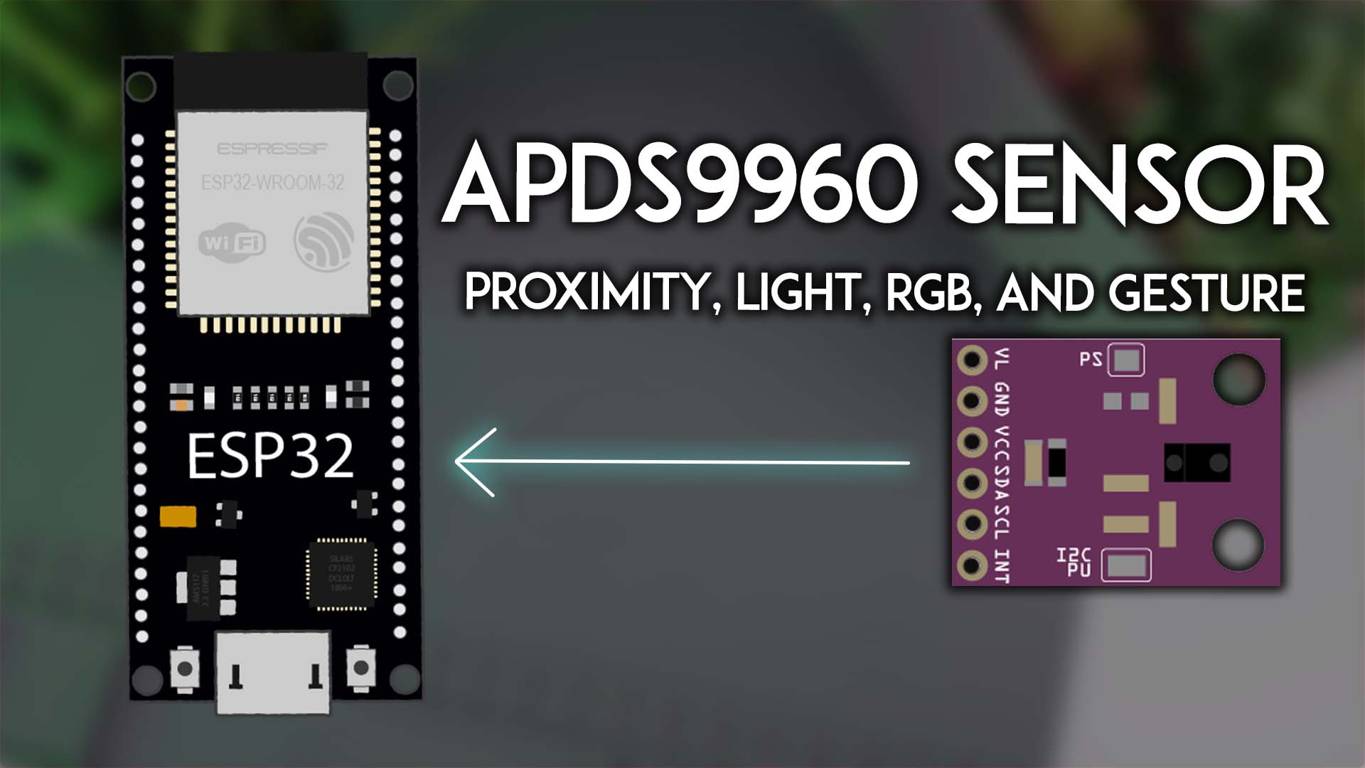
ESP32 with APDS9960 Proximity, Light, RGB, and Gesture Sensor (Arduino IDE)
Interface the APDS9960 sensor with the ESP32 using Arduino programming. This sensor combines gesture detection, proximity sensing, and ambient RGB light measurement over I2C.
- Suitable forB.Tech/Diploma IoT/ESP32 students
- Build time1-2 weeks
- LevelBeginner
- Available atAjvika Labs, Kakinada
About this project
Learn how to use the APDS9960 sensor with the ESP32 using Arduino IDE. This sensor combines gesture detection, proximity sensing, and ambient RGB light measurement over I2C. In this guide, we’ll show you how to wire the sensor to the ESP32 and the code to use each of its features.
Table of Contents
In this guide, we’ll cover the following topics:
Introducing the APDS9960 Sensor
Wiring the APDS9960 Module to the ESP32
Installing Libraries for the APDS9960 Sensor
Getting the Sensor I2C Address and Chip ID
Examples:
1) ESP32 with APDS9960 – Detecting Gestures
2) ESP32 with APDS9960 – Detecting Gestures and Display on OLED
3) ESP32 with APDS9960 – Detecting Proximity
4) ESP32 with APDS9960 – Detecting RGB Light
Prerequisites
This tutorial focuses on programming the ESP32 using the Arduino core. Before proceeding, you should have the ESP32 Arduino core installed in your Arduino IDE. Follow the next tutorial to install the ESP32 on the Arduino IDE, if you haven’t already.
Installing the ESP32 Board in Arduino IDE (Windows, Mac OS X, and Linux instructions)
Introducing the APDS9960 Sensor
The APDS9960 is a 4-in-one sensor that combines gesture detection, proximity sensing, ambient light, and RGB color sensing in one small module. It comes in a compact package with a built-in IR LED and a factory-calibrated LED driver. This sensor is used on the Samsung Galaxy S5 Smartphone.
For our ESP32 projects, it’s useful to get a breakout board with the sensor. I’ve got the breakout board shown in the picture below.
You can get different modules with the same sensor, but from different providers. They may look different, but they will work the same.
The module uses the I2C communication protocol, which makes it quite simple to incorporate into your
ESP32
ESP8266
Arduino
, or
Raspberry Pi Pico
projects.
For more detailed information about how the sensor works, we recommend taking a look at the
APDS9960 datasheet
Key Features of the APDS9960
Here’s a summary of the key features of the APDS9960 sensor:
Gesture Detection
: detects up, down, left, right, and other gestures using IR-based proximity.
Proximity Sensin
g: measures distance to objects typically up to 20 cm > analog output: 0–255 range.
Ambient Light Sensing
: measures ambient light intensity, useful to control the brightness of displays.
RGB Color Sensing
: detects red, green, blue, and clear light levels.
I2C Interface
: easy integration with microcontrollers like Arduino, ESP32, ESP8266, etc.
Operating Voltage
: 2.4V to 3.6V.
Where to Buy?
You can check our Maker Advisor Tools page to compare the APDS9960 module price in different stores:
APDS9960 Proximity, Light, RGB, Gesture Sensor
APDS9960 Sensor Module Pinout and Wiring
Let’s take a quick look at the APDS9960 sensor module pinout. If you have a different module, the pinout should be similar.
Pin
Function
Wiring to the ESP32
VCC
Power supply (2.4V to 3.6V)
3.3V
GND
Ground
GND
SDA
I2C data line
GPIO 21
SCL
I2C clock Line
GPIO 22
INT
Interrupt Output for the proximity sensor (active LOW)
Any digital pin
VL
Additional power supply for the IR LED
Usually, you don’t need to connect
Recommended reading
:
ESP32 I2C Communication: Set Pins, Multiple Bus Interfaces and Peripherals (Arduino IDE)
APDS9960 Jumpers:
The APDS9960 sensor module comes with two jumpers, which you’ll usually want to leave as they are:
PS Jumper
: the PS jumper connects the power for the sensor and its IR LED. By default, it’s closed (solder blob present), which means, the IR LED will get its power from the VCC pin. The VL pin can be left unconnected.
I2C PU Jumper
: connects 10K pull-up resistors to SDA/SCL (you don’t need to add resistors for the SDA and SCL lines to your circuit).
Wiring the APDS9960 Module to the ESP32
Here’s a list of the parts required for this tutorial:
ESP32 Board
– read
ESP32 Development Boards Review and Comparison
APDS9960 Sensor
LED
220 Ohm resistor
SSD1306 OLED Display
(optional)
Jumper wires
Breadboard
You can use the preceding links or go directly to
MakerAdvisor.com/tools
to find all the parts for your projects at the best price!
Wire the APDS9960 sensor to the ESP32 as shown in the following table/diagram.
Pin
Wiring to the ESP32
VCC
3.3V
GND
GND
SDA
GPIO 21
SCL
GPIO 22
INT
GPIO 4 (or any digital pin)
VL
don’t connect * (check your jumpers)
Recommended reading:
ESP32 Pinout Reference: Which GPIO pins should you use?
Installing Libraries for the APDS9960 Sensor
There are several libraries that make it easy to interface with the APDS9960 sensor. We’ll use the
APDS9960 library by Adafruit
. Install it on your Arduino IDE.
Go to
Sketch
>
Include Library
>
Manage Libraries
. Search for
APDS9960 Adafruit
and install the corresponding library and any additional required dependencies
Getting the Sensor I2C Address and Chip ID
The APDS9960 sensor typically uses the I2C address
0x39
and has a chip ID of
0xAB
However, some clone or counterfeit modules may use a different I2C address or return a different chip ID. To avoid issues, it’s a good idea to run the code below to confirm the actual address and ID of your sensor.
/*
Permission is hereby granted, free of charge, to any person obtaining a copy of this software and associated documentation files.
The above copyright notice and this permission notice shall be included in all copies or substantial portions of the Software.
*/
#include `Wire.h`
// Define APDS9960 chip ID register
#define APDS9960_ID_REG 0x92 // Chip ID register address
// Function to read chip ID from a given I2C address
uint8_t readChipID(uint8_t i2cAddress) {
Wire.beginTransmission(i2cAddress);
Wire.write(APDS9960_ID_REG); // Request chip ID register
Wire.endTransmission(false);
Wire.requestFrom(i2cAddress, (uint8_t)1);
if (Wire.available()) {
return Wire.read(); // Read chip ID
}
return 0; // Return 0 if no data (invalid or no response)
}
void setup() {
Serial.begin(115200);
delay(1000);
Serial.println(\"Starting I2C Scanner and Chip ID Reader\");
// Initialize I2C
Wire.begin();
Wire.setClock(100000);
// Scan I2C bus for devices
Serial.println(\"\
Scanning I2C bus...\");
bool deviceFound = false;
for (uint8_t address = 0x08; address <= 0x7F; address++) {
Wire.beginTransmission(address);
uint8_t error = Wire.endTransmission();
if (error == 0) {
deviceFound = true;
Serial.print(\"I2C device found at address 0x\");
if (address < 16) Serial.print(\"0\");
Serial.print(address, HEX);
// Read and print chip ID
uint8_t chipID = readChipID(address);
Serial.print(\" - Chip ID: 0x\");
if (chipID < 16) Serial.print(\"0\");
Serial.println(chipID, HEX);
}
}
if (!deviceFound) {
Serial.println(\"No I2C devices found. Check wiring or try again.\");
} else {
Serial.println(\"\
Scan complete.\");
}
}
void loop() {
}
After uploading the code, open the Serial Monitor at a baud rate of 115200. You should get your sensor I2C address and chip ID.
In my case, the I2C address is
0x39
, which is the expected address, and the chip ID is
0xA8
, which is
not what is expected
(
0xAB
would be expected). This means I have a counterfeit module.
If you also have a counterfeit module, don’t worry. You can still use it and follow the tutorial. You just need to make a small change in one of the library files.
APDS9960 – Not Expected Chip ID
The
Adafruit_APDS9960
library has the chip ID hardcoded, and it checks the sensor ID when initializing the module. If you have a counterfeit one, it won’t initialize properly.
To fix this, follow these steps:
Open the
Arduino IDE installation folder
and navigate to the
libraries
directory.
Locate the
Adafruit_APDS9960_Library
folder.
Inside it, open the
Adafruit_APDS9960.cpp
file.
Comm
Technologies used
Hardware components
- ESP32
- ESP8266
- Arduino
- Raspberry Pi
- SSD1306
- OLED
Software & tools
- Arduino IDE
What you get
- Working project / hardware kit, tested before delivery
- Complete source code with explanation
- Project demo and guidance for your viva
- Project report, PPT and IEEE paper support (on request)
Delivery & Payment
Delivery takes a minimum of two weeks from the date your inquiry is confirmed.
Payment is in two parts:
• 50% advance to start the project
• Remaining 50% before delivery
Note:
• Documentation and PPT are not included by default
• If you need documentation/PPT, it can be arranged for extra time and cost
We'll confirm the exact timeline and cost with you after reviewing your requirements.
Related IoT/ESP32 projects

IoT/ESP32
ESP32 External Wake Up from Deep Sleep
This article shows how to put the ESP32 in deep sleep mode and wake it with an external wake up like a button press. We'll cover how to use...
View project
IoT/ESP32
ESP32: Upload Files to LittleFS using Arduino IDE
Upload files to the ESP32 Filesystem (LittleFS) by using a plugin for Arduino IDE (1.8.X). The plugin lets you use three different filesyste...
View project
IoT/ESP32
ESP32: Guide for MicroSD Card Module using Arduino IDE
Use a microSD card with the ESP32: you'll learn how to read and write files to the microSD card. To interface a microSD card with an ESP32 b...
View project
IoT/ESP32
ESP32 Save Data Permanently using Preferences Library
Save data permanently on the ESP32 flash memory using Preferences.h library. The data held in the flash memory persists across resets or pow...
View project