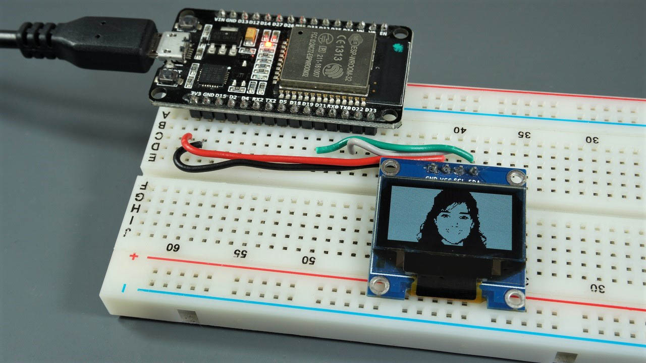
ESP32 OLED Display with Arduino IDE
This guide shows how to use the 0.96 inch SSD1306 OLED display with ESP32 using Arduino IDE. Learn how to write text, set different fonts, draw shapes and display bitmaps images.
- Suitable forB.Tech/Diploma IoT/ESP32 students
- Build time1-2 weeks
- LevelBeginner
- Available atAjvika Labs, Kakinada
About this project
This guide shows how to use the 0.96 inch SSD1306 OLED display with ESP32 using Arduino IDE. We’ll show you how to write text, set different fonts, draw shapes and display bitmaps images.
We also have a dedicated guide that shows how to
display temperature and humidity readings using DHT sensor and ESP32
Introducing 0.96 inch OLED Display
The
OLED display
that we’ll use in this tutorial is the SSD1306 model: a monocolor, 0.96 inch display with 128×64 pixels as shown in the following figure.
The OLED display doesn’t require backlight, which results in a very nice contrast in dark environments. Additionally, its pixels consume energy only when they are on, so the OLED display consumes less power when compared to other displays.
The model we’re using has four pins and communicates with any microcontroller using I2C communication protocol. There are models that come with an extra RESET pin or that communicate using SPI communication protocol.
OLED Display SSD1306 Pin Wiring
Because the OLED display uses I2C communication protocol, wiring is very simple. You can use the following table as a reference.
Pin
ESP32
Vin
3.3V
GND
GND
SCL
GPIO 22
SDA
GPIO 21
Alternatively, you can follow the next schematic diagram to wire the ESP32 to the OLED display.
In this example, we’re using I2C communication protocol. The most suitable pins for I2C communication in the ESP32 are
GPIO 22
(SCL) and
GPIO 21
(SDA).
If you’re using an OLED display with SPI communication protocol, use the following GPIOs.
GPIO 18: CLK
GPIO 19: MISO
GPIO 23: MOSI
GPIO 5: CS
Read our
ESP32 Pinout Reference Guide
to learn more about the ESP32 GPIOs.
Installing SSD1306 OLED Library – ESP32
There are several libraries available to control the OLED display with the ESP32. In this tutorial we’ll use two Adafruit libraries:
Adafruit_SSD1306 library
and
Adafruit_GFX library
Follow the next steps to install those libraries.
1. Open your Arduino IDE and go to
Sketch
>
Include Library
>
Manage Libraries
. The Library Manager should open.
2. Type “
SSD1306
” in the search box and install the SSD1306 library from Adafruit.
3. After installing the SSD1306 library from Adafruit, type “
GFX
” in the search box and install the library.
4. After installing the libraries, restart your Arduino IDE.
We’ll program the ESP32 using Arduino IDE, so you must have the ESP32 add-on installed in your Arduino IDE. If you haven’t, follow the next tutorial first:
Install the ESP32 Board in Arduino IDE (Windows instructions)
Install the ESP32 Board in Arduino IDE (Mac OS X and Linux instructions)
Testing OLED Display with ESP32
After wiring the OLED display to the ESP32 and installing all required libraries, you can use one example from the library to see if everything is working properly.
In your Arduino IDE, go to
File
>
Examples
>
Adafruit SSD1306
and select the example for the display you’re using.
The following code should load:
/*********
This is an example for our Monochrome OLEDs based on SSD1306 drivers. Pick one up today in the adafruit shop! ------> http://www.adafruit.com/category/63_98
This example is for a 128x32 pixel display using I2C to communicate 3 pins are required to interface (two I2C and one reset).
Adafruit invests time and resources providing this open source code, please support Adafruit and open-source hardware by purchasing products from Adafruit!
Written by Limor Fried/Ladyada for Adafruit Industries, with contributions from the open source community. BSD license, check license.txt for more information All text above, and the splash screen below must be included in any redistribution.
*********/
#include `SPI.h`
#include `Wire.h`
#include `Adafruit_GFX.h`
#include `Adafruit_SSD1306.h`
#define SCREEN_WIDTH 128 // OLED display width, in pixels
#define SCREEN_HEIGHT 64 // OLED display height, in pixels
// Declaration for an SSD1306 display connected to I2C (SDA, SCL pins)
#define OLED_RESET -1 // Reset pin # (or -1 if sharing Arduino reset pin)
Adafruit_SSD1306 display(SCREEN_WIDTH, SCREEN_HEIGHT, &Wire, OLED_RESET);
#define NUMFLAKES 10 // Number of snowflakes in the animation example
#define LOGO_HEIGHT 16
#define LOGO_WIDTH 16
static const unsigned char PROGMEM logo_bmp[] =
{ B00000000, B11000000,
B00000001, B11000000,
B00000001, B11000000,
B00000011, B11100000,
B11110011, B11100000,
B11111110, B11111000,
B01111110, B11111111,
B00110011, B10011111,
B00011111, B11111100,
B00001101, B01110000,
B00011011, B10100000,
B00111111, B11100000,
B00111111, B11110000,
B01111100, B11110000,
B01110000, B01110000,
B00000000, B00110000 };
void setup() {
Serial.begin(115200);
// SSD1306_SWITCHCAPVCC = generate display voltage from 3.3V internally
if(!display.begin(SSD1306_SWITCHCAPVCC, 0x3C)) {
Serial.println(F(\"SSD1306 allocation failed\"));
for(;;); // Don't proceed, loop forever
}
// Show initial display buffer contents on the screen --
// the library initializes this with an Adafruit splash screen.
display.display();
delay(2000); // Pause for 2 seconds
// Clear the buffer
display.clearDisplay();
// Draw a single pixel in white
display.drawPixel(10, 10, WHITE);
// Show the display buffer on the screen. You MUST call display() after
// drawing commands to make them visible on screen!
display.display();
delay(2000);
// display.display() is NOT necessary after every single drawing command,
// unless that's what you want...rather, you can batch up a bunch of
// drawing operations and then update the screen all at once by calling
// display.display(). These examples demonstrate both approaches...
testdrawline(); // Draw many lines
testdrawrect(); // Draw rectangles (outlines)
testfillrect(); // Draw rectangles (filled)
testdrawcircle(); // Draw circles (outlines)
testfillcircle(); // Draw circles (filled)
testdrawroundrect(); // Draw rounded rectangles (outlines)
testfillroundrect(); // Draw rounded rectangles (filled)
testdrawtriangle(); // Draw triangles (outlines)
testfilltriangle(); // Draw triangles (filled)
testdrawchar(); // Draw characters of the default font
testdrawstyles(); // Draw 'stylized' characters
testscrolltext(); // Draw scrolling text
testdrawbitmap(); // Draw a small bitmap image
// Invert and restore display, pausing in-between
display.invertDisplay(true);
delay(1000);
display.invertDisplay(false);
delay(1000);
testanimate(logo_bmp, LOGO_WIDTH, LOGO_HEIGHT); // Animate bitmaps
}
void loop() {
}
void testdrawline() {
int16_t i;
display.clearDisplay(); // Clear display buffer
for(i=0; i<display.width(); i+=4) {
display.drawLine(0, 0, i, display.height()-1, WHITE);
display.display(); // Update screen with each newly-drawn line
delay(1);
}
for(i=0; i<display.height(); i+=4) {
display.drawLine(0, 0, display.width()-1, i, WHITE);
display.display();
delay(1);
}
delay(250);
display.clearDisplay();
for(i=0; i<display.width(); i+=4) {
display.drawLine(0, display.height()-1, i, 0, WHITE);
display.display();
delay(1);
}
for(i=display.height()-1; i>=0; i-=4) {
display.drawLine(0, display.height()-1, display.width()-1, i, WHITE);
display.display();
delay(1);
}
delay(250);
display.clearDisplay();
for(i=display.width()-1; i>=0; i-=4) {
display.drawLine(display.width()-1, display.height()-1, i, 0, WHITE);
display.display();
delay(1);
}
for(i=display.height()-1; i>=0; i-=4) {
display.drawLine(display.width()-1, display.height()-1, 0, i, WHITE);
display.display();
delay(1);
}
delay(250);
display.clearDisplay();
for(i=0; i<display.height(); i+=4) {
display.drawLine(display.width()-1, 0, 0, i, WHITE);
display.display();
delay(1);
}
for(i=0; i<display.width(); i+=4) {
displa
We also have a dedicated guide that shows how to
display temperature and humidity readings using DHT sensor and ESP32
Introducing 0.96 inch OLED Display
The
OLED display
that we’ll use in this tutorial is the SSD1306 model: a monocolor, 0.96 inch display with 128×64 pixels as shown in the following figure.
The OLED display doesn’t require backlight, which results in a very nice contrast in dark environments. Additionally, its pixels consume energy only when they are on, so the OLED display consumes less power when compared to other displays.
The model we’re using has four pins and communicates with any microcontroller using I2C communication protocol. There are models that come with an extra RESET pin or that communicate using SPI communication protocol.
OLED Display SSD1306 Pin Wiring
Because the OLED display uses I2C communication protocol, wiring is very simple. You can use the following table as a reference.
Pin
ESP32
Vin
3.3V
GND
GND
SCL
GPIO 22
SDA
GPIO 21
Alternatively, you can follow the next schematic diagram to wire the ESP32 to the OLED display.
In this example, we’re using I2C communication protocol. The most suitable pins for I2C communication in the ESP32 are
GPIO 22
(SCL) and
GPIO 21
(SDA).
If you’re using an OLED display with SPI communication protocol, use the following GPIOs.
GPIO 18: CLK
GPIO 19: MISO
GPIO 23: MOSI
GPIO 5: CS
Read our
ESP32 Pinout Reference Guide
to learn more about the ESP32 GPIOs.
Installing SSD1306 OLED Library – ESP32
There are several libraries available to control the OLED display with the ESP32. In this tutorial we’ll use two Adafruit libraries:
Adafruit_SSD1306 library
and
Adafruit_GFX library
Follow the next steps to install those libraries.
1. Open your Arduino IDE and go to
Sketch
>
Include Library
>
Manage Libraries
. The Library Manager should open.
2. Type “
SSD1306
” in the search box and install the SSD1306 library from Adafruit.
3. After installing the SSD1306 library from Adafruit, type “
GFX
” in the search box and install the library.
4. After installing the libraries, restart your Arduino IDE.
We’ll program the ESP32 using Arduino IDE, so you must have the ESP32 add-on installed in your Arduino IDE. If you haven’t, follow the next tutorial first:
Install the ESP32 Board in Arduino IDE (Windows instructions)
Install the ESP32 Board in Arduino IDE (Mac OS X and Linux instructions)
Testing OLED Display with ESP32
After wiring the OLED display to the ESP32 and installing all required libraries, you can use one example from the library to see if everything is working properly.
In your Arduino IDE, go to
File
>
Examples
>
Adafruit SSD1306
and select the example for the display you’re using.
The following code should load:
/*********
This is an example for our Monochrome OLEDs based on SSD1306 drivers. Pick one up today in the adafruit shop! ------> http://www.adafruit.com/category/63_98
This example is for a 128x32 pixel display using I2C to communicate 3 pins are required to interface (two I2C and one reset).
Adafruit invests time and resources providing this open source code, please support Adafruit and open-source hardware by purchasing products from Adafruit!
Written by Limor Fried/Ladyada for Adafruit Industries, with contributions from the open source community. BSD license, check license.txt for more information All text above, and the splash screen below must be included in any redistribution.
*********/
#include `SPI.h`
#include `Wire.h`
#include `Adafruit_GFX.h`
#include `Adafruit_SSD1306.h`
#define SCREEN_WIDTH 128 // OLED display width, in pixels
#define SCREEN_HEIGHT 64 // OLED display height, in pixels
// Declaration for an SSD1306 display connected to I2C (SDA, SCL pins)
#define OLED_RESET -1 // Reset pin # (or -1 if sharing Arduino reset pin)
Adafruit_SSD1306 display(SCREEN_WIDTH, SCREEN_HEIGHT, &Wire, OLED_RESET);
#define NUMFLAKES 10 // Number of snowflakes in the animation example
#define LOGO_HEIGHT 16
#define LOGO_WIDTH 16
static const unsigned char PROGMEM logo_bmp[] =
{ B00000000, B11000000,
B00000001, B11000000,
B00000001, B11000000,
B00000011, B11100000,
B11110011, B11100000,
B11111110, B11111000,
B01111110, B11111111,
B00110011, B10011111,
B00011111, B11111100,
B00001101, B01110000,
B00011011, B10100000,
B00111111, B11100000,
B00111111, B11110000,
B01111100, B11110000,
B01110000, B01110000,
B00000000, B00110000 };
void setup() {
Serial.begin(115200);
// SSD1306_SWITCHCAPVCC = generate display voltage from 3.3V internally
if(!display.begin(SSD1306_SWITCHCAPVCC, 0x3C)) {
Serial.println(F(\"SSD1306 allocation failed\"));
for(;;); // Don't proceed, loop forever
}
// Show initial display buffer contents on the screen --
// the library initializes this with an Adafruit splash screen.
display.display();
delay(2000); // Pause for 2 seconds
// Clear the buffer
display.clearDisplay();
// Draw a single pixel in white
display.drawPixel(10, 10, WHITE);
// Show the display buffer on the screen. You MUST call display() after
// drawing commands to make them visible on screen!
display.display();
delay(2000);
// display.display() is NOT necessary after every single drawing command,
// unless that's what you want...rather, you can batch up a bunch of
// drawing operations and then update the screen all at once by calling
// display.display(). These examples demonstrate both approaches...
testdrawline(); // Draw many lines
testdrawrect(); // Draw rectangles (outlines)
testfillrect(); // Draw rectangles (filled)
testdrawcircle(); // Draw circles (outlines)
testfillcircle(); // Draw circles (filled)
testdrawroundrect(); // Draw rounded rectangles (outlines)
testfillroundrect(); // Draw rounded rectangles (filled)
testdrawtriangle(); // Draw triangles (outlines)
testfilltriangle(); // Draw triangles (filled)
testdrawchar(); // Draw characters of the default font
testdrawstyles(); // Draw 'stylized' characters
testscrolltext(); // Draw scrolling text
testdrawbitmap(); // Draw a small bitmap image
// Invert and restore display, pausing in-between
display.invertDisplay(true);
delay(1000);
display.invertDisplay(false);
delay(1000);
testanimate(logo_bmp, LOGO_WIDTH, LOGO_HEIGHT); // Animate bitmaps
}
void loop() {
}
void testdrawline() {
int16_t i;
display.clearDisplay(); // Clear display buffer
for(i=0; i<display.width(); i+=4) {
display.drawLine(0, 0, i, display.height()-1, WHITE);
display.display(); // Update screen with each newly-drawn line
delay(1);
}
for(i=0; i<display.height(); i+=4) {
display.drawLine(0, 0, display.width()-1, i, WHITE);
display.display();
delay(1);
}
delay(250);
display.clearDisplay();
for(i=0; i<display.width(); i+=4) {
display.drawLine(0, display.height()-1, i, 0, WHITE);
display.display();
delay(1);
}
for(i=display.height()-1; i>=0; i-=4) {
display.drawLine(0, display.height()-1, display.width()-1, i, WHITE);
display.display();
delay(1);
}
delay(250);
display.clearDisplay();
for(i=display.width()-1; i>=0; i-=4) {
display.drawLine(display.width()-1, display.height()-1, i, 0, WHITE);
display.display();
delay(1);
}
for(i=display.height()-1; i>=0; i-=4) {
display.drawLine(display.width()-1, display.height()-1, 0, i, WHITE);
display.display();
delay(1);
}
delay(250);
display.clearDisplay();
for(i=0; i<display.height(); i+=4) {
display.drawLine(display.width()-1, 0, 0, i, WHITE);
display.display();
delay(1);
}
for(i=0; i<display.width(); i+=4) {
displa
Technologies used
Hardware components
- ESP32
- Arduino
- SSD1306
- OLED
Software & tools
- Arduino IDE
What you get
- Working project / hardware kit, tested before delivery
- Complete source code with explanation
- Project demo and guidance for your viva
- Project report, PPT and IEEE paper support (on request)
Delivery & Payment
Delivery takes a minimum of two weeks from the date your inquiry is confirmed.
Payment is in two parts:
• 50% advance to start the project
• Remaining 50% before delivery
Note:
• Documentation and PPT are not included by default
• If you need documentation/PPT, it can be arranged for extra time and cost
We'll confirm the exact timeline and cost with you after reviewing your requirements.
Related IoT/ESP32 projects

IoT/ESP32
ESP32 External Wake Up from Deep Sleep
This article shows how to put the ESP32 in deep sleep mode and wake it with an external wake up like a button press. We'll cover how to use...
View project
IoT/ESP32
ESP32: Upload Files to LittleFS using Arduino IDE
Upload files to the ESP32 Filesystem (LittleFS) by using a plugin for Arduino IDE (1.8.X). The plugin lets you use three different filesyste...
View project
IoT/ESP32
ESP32: Guide for MicroSD Card Module using Arduino IDE
Use a microSD card with the ESP32: you'll learn how to read and write files to the microSD card. To interface a microSD card with an ESP32 b...
View project
IoT/ESP32
ESP32 Save Data Permanently using Preferences Library
Save data permanently on the ESP32 flash memory using Preferences.h library. The data held in the flash memory persists across resets or pow...
View project