ESP32 MQTT – Publish and Subscribe with Arduino IDE
This project shows how to use MQTT communication protocol with the ESP32 to publish messages and subscribe to topics. We’ll publish readings from a BME280 sensor and control an output. The ESP32 we’ll be programmed using Arduino IDE.
- Suitable forB.Tech/Diploma IoT/ESP32 students
- Build time1-2 weeks
- LevelBeginner
- Available atAjvika Labs, Kakinada
About this project
Project Overview
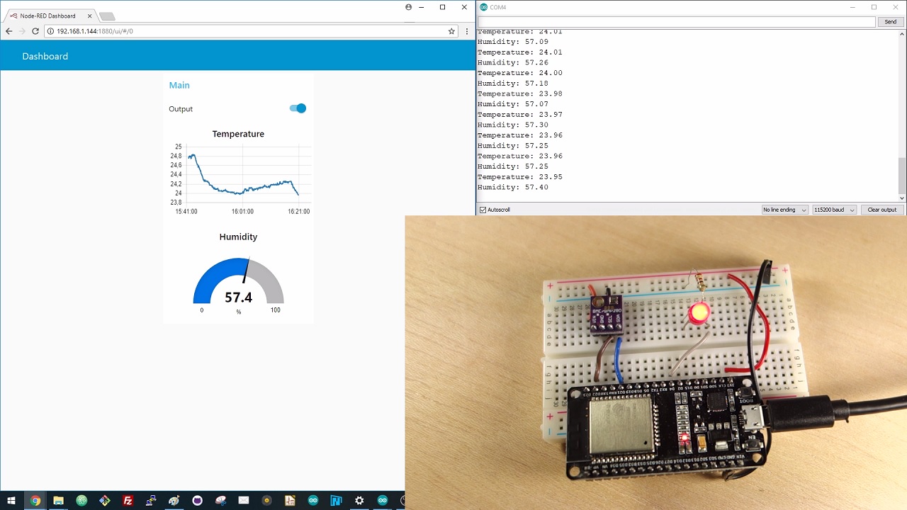
In this example, there’s a Node-RED application that controls ESP32 outputs and receives sensor readings from the ESP32 using MQTT communication protocol. The Node-RED application is running on a Raspberry Pi.
We’ll use the
Mosquitto broker installed
on the same Raspberry Pi. The broker is responsible for receiving all messages, filtering the messages, decide who is interested in them and publishing the messages to all subscribed clients.
The following figure shows an overview of what we’re going to do in this tutorial.
The Node-RED application publishes messages (“
on
” or “
off
“) in the topic
esp32/output
. The ESP32 is subscribed to that topic. So, it receives the message with “on” or “off” to turn the LED on or off.
The ESP32 publishes temperature on the
esp32/temperature
topic and the humidity on the
esp32/humidity
topic. The Node-RED application is subscribed to those topics. So, it receives temperature and humidity readings that can be displayed on a chart or gauge, for example.
Note:
there’s also a similar tutorial on how to use the
ESP8266 and Node-RED with MQTT
Prerequisites
You should be familiar with the Raspberry Pi –
read Getting Started with Raspberry Pi
You should have the Raspbian operating system installed in your Raspberry Pi –
read Installing Raspbian Lite, Enabling and Connecting with SSH
You need
Node-RED installed on your Pi
and
Node-RED Dashboard
Learn
what’s MQTT and how it works
If you like home automation and you want to learn more about Node-RED, Raspberry Pi, ESP8266 and Arduino, we recommend trying our course:
Build a Home Automation System with Node-RED, ESP8266 and Arduino
. We also have a course dedicated to the ESP32: Enroll in
Learn ESP32 with Arduino IDE
course.
Parts Required
These are the parts required to build the circuit (click the links below to find the best price at
Maker Advisor
):
Raspberry Pi
–
read Best Raspberry Pi 3 Starter Kits
ESP32 DOIT DEVKIT V1 Board
–
read ESP32 Development Boards Review and Comparison
BME280 sensor module
1x 5mm LED
1x 220 Ohm resistor
Breadboard
Jumper wires
You can use the preceding links or go directly to
MakerAdvisor.com/tools
to find all the parts for your projects at the best price!
Introducing the BME280 Sensor Module
The
BME280 sensor module
reads temperature, humidity, and pressure. Because pressure changes with altitude, you can also estimate altitude. However, in this tutorial we’ll just read temperature and humidity. There are several versions of this sensor module, but we’re using the one shown in the figure below.
The sensor can communicate using either SPI or I2C communication protocols (there are modules of this sensor that just communicate with I2C, these just come with four pins).
To use SPI communication protocol, use the following pins:
SCK – this is the SPI Clock pin
SDO – MISO
SDI – MOSI
CS – Chip Select
To use I2C communication protocol, the sensor uses the following pins:
SCK – SCL pin
SDI – SDA pin
Schematic
We’re going to use I2C communication with the BME280 sensor module. For that, wire the sensor to the ESP32 SDA and SCL pins, as shown in the following schematic diagram.
We’ll also control an ESP32 output, an LED connected to GPIO 4.
Here’s how your circuit should look:
Preparing the Arduino IDE
There’s an add-on for the Arduino IDE that allows you to program the ESP32 using the Arduino IDE and its programming language. Follow one of the next tutorials to prepare your Arduino IDE to work with the ESP32, if you haven’t already.
Windows
instructions – ESP32 Board in Arduino IDE
Mac and Linux
instructions – ESP32 Board in Arduino IDE
After making sure you have the ESP32 add-on installed, you can continue with this tutorial.
Installing the PubSubClient Library
The
PubSubClient
library provides a client for doing simple publish/subscribe messaging with a server that supports MQTT (basically allows your ESP32 to talk with Node-RED).
Click here to download the PubSubClient library
. You should have a
.zip
folder in your Downloads folder
Unzip the
.zip
folder and you should get
pubsubclient-master
folder
Rename your folder from
pubsubclient-master
to
pubsubclient
Move the
pubsubclient
folder to your Arduino IDE installation libraries folder
Then, re-open your Arduino IDE
The library comes with a number of example sketches. See
File
>
Examples
>
PubSubClient
within the Arduino IDE software.
Important:
PubSubClient is not fully compatible with the ESP32, but the example provided in this tutorial is working very reliably during our tests.
Installing the BME280 library
To take readings from the BME280 sensor module we’ll use the
Adafruit_BME280 library
. Follow the next steps to install the library in your Arduino IDE:
Click here to download
the Adafruit-BME280 library. You should have a .zip folder in your Downloads folder
Unzip the .zip folder and you should get
Adafruit-BME280-Library-master
folder
Rename your folder from
Adafruit-BME280-Library-master
to
Adafruit_BME280_Library
Move the
Adafruit_BMPE280_Library
folder to your Arduino IDE installation libraries folder
Finally, re-open your Arduino IDE
Alternatively, you can go to
Sketch
>
Include Library
>
Manage Libraries
and type “
adafruit bme280
” to search for the library. Then, click install.
Installing the Adafruit_Sensor library
To use the BME280 library, you also need to install the
Adafruit_Sensor library
. Follow the next steps to install the library:
Click here to download
the Adafruit_Sensor library. You should have a .zip folder in your Downloads folder
Unzip the .zip folder and you should get
Adafruit_Sensor-master
folder
Rename your folder from
Adafruit_Sensor-master
to
Adafruit_Sensor
Move the
Adafruit_Sensor
folder to your Arduino IDE installation libraries folder
Finally, re-open your Arduino IDE
Uploading code
Now, you can upload the following code to your ESP32. The code is commented on where you need to make changes.
You need to edit the code with your own SSID, password and Raspberry Pi IP address.
#include `WiFi.h`
#include `PubSubClient.h`
#include `Wire.h`
#include `Adafruit_BME280.h`
#include `Adafruit_Sensor.h`
// Replace the next variables with your SSID/Password combination
const char* ssid = \"REPLACE_WITH_YOUR_SSID\";
const char* password = \"REPLACE_WITH_YOUR_PASSWORD\";
// Add your MQTT Broker IP address, example:
//const char* mqtt_server = \"192.168.1.144\";
const char* mqtt_server = \"YOUR_MQTT_BROKER_IP_ADDRESS\";
WiFiClient espClient;
PubSubClient client(espClient);
long lastMsg = 0;
char msg[50];
int value = 0;
//uncomment the following lines if you're using SPI
/*#include `SPI.h`
#define BME_SCK 18
#define BME_MISO 19
#define BME_MOSI 23
#define BME_CS 5*/
Adafruit_BME280 bme; // I2C
//Adafruit_BME280 bme(BME_CS); // hardware SPI
//Adafruit_BME280 bme(BME_CS, BME_MOSI, BME_MISO, BME_SCK); // software SPI
float temperature = 0;
float humidity = 0;
// LED Pin
const int ledPin = 4;
void setup() {
Serial.begin(115200);
// default settings
// (you can also pass in a Wire library object like &Wire2)
//status = bme.begin();
if (!bme.begin(0x76)) {
Serial.println(\"Could not find a valid BME280 sensor, check wiring!\");
while (1);
}
setup_wifi();
client.setServer(mqtt_server, 1883);
client.setCallback(callback);
pinMode(ledPin, OUTPUT);
}
void setup_wifi() {
delay(10);
// We start by connecting to a WiFi network
Serial.println();
Serial.print(\"Connecting to \");
Serial.println(ssid);
WiFi.begin(ssid, password);
while (WiFi.status() != WL_CONNECTED) {
delay(500);
Serial.print(\"
Technologies used
Hardware components
- ESP32
- ESP8266
- Arduino
- Raspberry Pi
- BME280
Software & tools
- Arduino IDE
- Node-RED
- MQTT
What you get
- Working project / hardware kit, tested before delivery
- Complete source code with explanation
- Project demo and guidance for your viva
- Project report, PPT and IEEE paper support (on request)
Related IoT/ESP32 projects

ESP32 External Wake Up from Deep Sleep
This article shows how to put the ESP32 in deep sleep mode and wake it with an external wake up like a button press. We'll cover how to use...
View project
ESP32: Upload Files to LittleFS using Arduino IDE
Upload files to the ESP32 Filesystem (LittleFS) by using a plugin for Arduino IDE (1.8.X). The plugin lets you use three different filesyste...
View project
ESP32: Guide for MicroSD Card Module using Arduino IDE
Use a microSD card with the ESP32: you'll learn how to read and write files to the microSD card. To interface a microSD card with an ESP32 b...
View project
ESP32 Save Data Permanently using Preferences Library
Save data permanently on the ESP32 flash memory using Preferences.h library. The data held in the flash memory persists across resets or pow...
View project