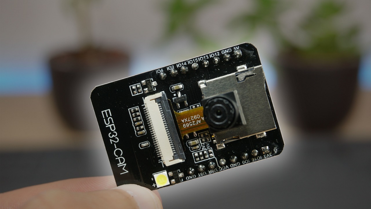
ESP32-CAM Video Streaming and Face Recognition with Arduino IDE
This article is a quick getting started guide for the ESP32-CAM board. We’ll show you how to setup a video streaming web server with face recognition and detection in less than 5 minutes with Arduino IDE.
- Suitable forB.Tech/Diploma IoT/ESP32 students
- Build time1-2 weeks
- LevelAdvanced
- Available atAjvika Labs, Kakinada
About this project
Note:
in this tutorial we use the example from the arduino-esp32 library. This tutorial doesn’t cover how to modify the example.
Important:
Unfortunately, the latest version of the example no longer covers face detection and recognition.
Related project:
ESP32-CAM Video Streaming Web Server
(works with Home Assistant and Node-Red)
Parts Required
To follow this tutorial you need the following components:
ESP32-CAM with OV2640
– read
Best ESP32-CAM Dev Boards
FTDI programmer
Female-to-female jumper wires
You can use the preceding links or go directly to
MakerAdvisor.com/tools
to find all the parts for your projects at the best price!
Introducing the ESP32-CAM
The
ESP32-CAM
is a very small camera module with the ESP32-S chip that costs approximately $10. Besides the OV2640 camera, and several GPIOs to connect peripherals, it also features a microSD card slot that can be useful to store images taken with the camera or to store files to serve to clients.
Image source – Seeed Studio
The
ESP32-CAM
doesn’t come with a USB connector, so you need an
FTDI programmer
to upload code through the
U0R
and
U0T
pins (serial pins).
Or, you can also use an
ESP32-MB programmer
. This micro USB programmer works like a shield that you attach to the ESP32-CAM board. The programmer comes with a USB socket that you connect directly to your computer.
Features
Here is a list with the ESP32-CAM features:
The smallest 802.11b/g/n Wi-Fi BT SoC module
Low power 32-bit CPU, can also serve the application processor
Up to 160MHz clock speed, summary computing power up to 600 DMIPS
Built-in 520 KB SRAM, external 4MPSRAM
Supports UART/SPI/I2C/PWM/ADC/DAC
Support OV2640 and OV7670 cameras, built-in flash lamp
Support image WiFI upload
Support TF card
Supports multiple sleep modes
Embedded Lwip and FreeRTOS
Supports STA/AP/STA+AP operation mode
Support Smart Config/AirKiss technology
Support for serial port local and remote firmware upgrades (FOTA)
ESP32-CAM Pinout
The following figure shows the ESP32-CAM pinout (AI-Thinker module).
Image source – Seeed Studio
There are three
GND
pins and two pins for power: either
3.3V
or
5V
GPIO 1
and
GPIO 3
are the serial pins. You need these pins to upload code to your board. Additionally,
GPIO 0
also plays an important role, since it determines whether the ESP32 is in flashing mode or not. When
GPIO 0
is connected to
GND
, the ESP32 is in flashing mode.
The following pins are internally connected to the microSD card reader:
GPIO 14: CLK
GPIO 15: CMD
GPIO 2: Data 0
GPIO 4: Data 1 (also connected to the on-board LED)
GPIO 12: Data 2
GPIO 13: Data 3
Video Streaming Server
Follow the next steps to build a video streaming web server with the ESP32-CAM that you can access on your local network.
Important:
Make sure you have your Arduino IDE updated as well as the latest version of the ESP32 add-on.
1. Install the ESP32 add-on
In this example, we use Arduino IDE to program the ESP32-CAM board. So, you need to have Arduino IDE installed as well as the ESP32 add-on. Follow the next tutorial to install the ESP32 add-on, if you haven’t already:
Installing ESP32 Board in Arduino IDE 2 (Windows, Mac OS X, Linux)
2. CameraWebServer Example Code
In your Arduino IDE, go to
File
>
Examples
>
ESP32
>
Camera
and open the
CameraWebServer
example.
The following code should load.
Before uploading the code, you need to insert your network credentials in the following variables:
const char* ssid = \"REPLACE_WITH_YOUR_SSID\";
const char* password = \"REPLACE_WITH_YOUR_PASSWORD\";
Then, make sure you select the right camera module. In this case, we’re using the AI-THINKER Model.
So, comment all the other models and uncomment the
CAMERA_MODEL_AI_THINKER
:
// Select camera model
//#define CAMERA_MODEL_WROVER_KIT
//#define CAMERA_MODEL_ESP_EYE
//#define CAMERA_MODEL_M5STACK_PSRAM
//#define CAMERA_MODEL_M5STACK_WIDE
#define CAMERA_MODEL_AI_THINKER
If none of the available options correspond to the camera you’re using, you need to add the pin assignment for your specific board in the
camera_pins.h
tab.
Now, the code is ready to be uploaded to your ESP32.
3. ESP32-CAM Upload Code
Connect the ESP32-CAM board to your computer using an FTDI programmer. Follow the next schematic diagram:
Many FTDI programmers have a jumper that allows you to select 3.3V or 5V. Make sure the jumper is in the right place to select 5V.
Important:
GPIO 0
needs to be connected to
GND
so that you’re able to upload code.
ESP32-CAM
FTDI Programmer
GND
GND
5V
VCC (5V)
U0R
TX
U0T
RX
GPIO 0
GND
Alternatively, connect your board to the MB-programmer.
To upload the code, follow the next steps:
1) Go to
Tools
>
Board
and select
AI-Thinker ESP32-CAM
2) Go to
Tools
>
Port
and select the COM port the ESP32 is connected to.
3) Then, click the upload button to upload the code.
4) When you start to see some dots on the debugging window, you may need to press the ESP32-CAM on-board RST button if it doesn’t go automatically into flashing mode.
After a few seconds, the code should be successfully uploaded to your board.
Getting the IP address
After uploading the code, disconnect
GPIO 0
from
GND
Open the Serial Monitor at a baud rate of 115200. Press the ESP32-CAM on-board Reset button.
The ESP32 IP address should be printed in the Serial Monitor.
Accessing the Video Streaming Server
Now, you can access your camera streaming server on your local network. Open a browser and type the ESP32-CAM IP address. Press the
Start Streaming
button to start video streaming.
You also have the option to take photos by clicking the
Get Still
button. Unfortunately, this example doesn’t save the photos, but you can modify it to use the on board microSD Card to store the captured photos.
There are also several camera settings that you can play with to adjust the image settings.
Finally, you can do face recognition and detection.
First, you need to enroll a new face. It will make several attempts to save the face. After enrolling a new user, it should detect the face later on (subject 0).
And that’s it. Now you have your video streaming web server up and running with face detection and recognition with the example from the library.
Troubleshooting
If you’re getting any of the following errors, read our
ESP32-CAM Troubleshooting Guide: Most Common Problems Fixed
Failed to connect to ESP32: Timed out waiting for packet header
Camera init failed with error 0x20001 or similar
Brownout detector or Guru meditation error
Sketch too big error – Wrong partition scheme selected
Board at COMX is not available – COM Port Not Selected
Psram error: GPIO isr service is not installed
Weak Wi-Fi Signal
No IP Address in Arduino IDE Serial Monitor
Can’t open web server
The image lags/shows lots of latency
Learn how to program and build 17 projects with the ESP32-CAM using Arduino IDE
Learn how to program and build 17 projects with the ESP32-CAM using Arduino IDE
Wrapping Up
The ESP32-CAM provides an inexpensive way to build more advanced home automation projects that feature video, taking photos, and face recognition.
In this tutorial we’ve tested the CameraWebServer example to test the camera functionalities. Now, the idea is to modify the example or write a completely new code to build other projects. For example,
take photos and save them to the microSD card when motion is detected
integrate video streaming in your home automation platform (like Node-RED or Home Assistant)
, and much more.
We hope you’ve find this tutorial useful. If you don’t have an ESP32-CAM yet, you can
grab it here
If you like this pr
Technologies used
Hardware components
- ESP32
- ESP32-CAM
- Arduino
- SD Card
Software & tools
- Arduino IDE
- Node-RED
- Home Assistant
What you get
- Working project / hardware kit, tested before delivery
- Complete source code with explanation
- Project demo and guidance for your viva
- Project report, PPT and IEEE paper support (on request)
Related IoT/ESP32 projects

ESP32 External Wake Up from Deep Sleep
This article shows how to put the ESP32 in deep sleep mode and wake it with an external wake up like a button press. We'll cover how to use...
View project
ESP32: Upload Files to LittleFS using Arduino IDE
Upload files to the ESP32 Filesystem (LittleFS) by using a plugin for Arduino IDE (1.8.X). The plugin lets you use three different filesyste...
View project
ESP32: Guide for MicroSD Card Module using Arduino IDE
Use a microSD card with the ESP32: you'll learn how to read and write files to the microSD card. To interface a microSD card with an ESP32 b...
View project
ESP32 Save Data Permanently using Preferences Library
Save data permanently on the ESP32 flash memory using Preferences.h library. The data held in the flash memory persists across resets or pow...
View project