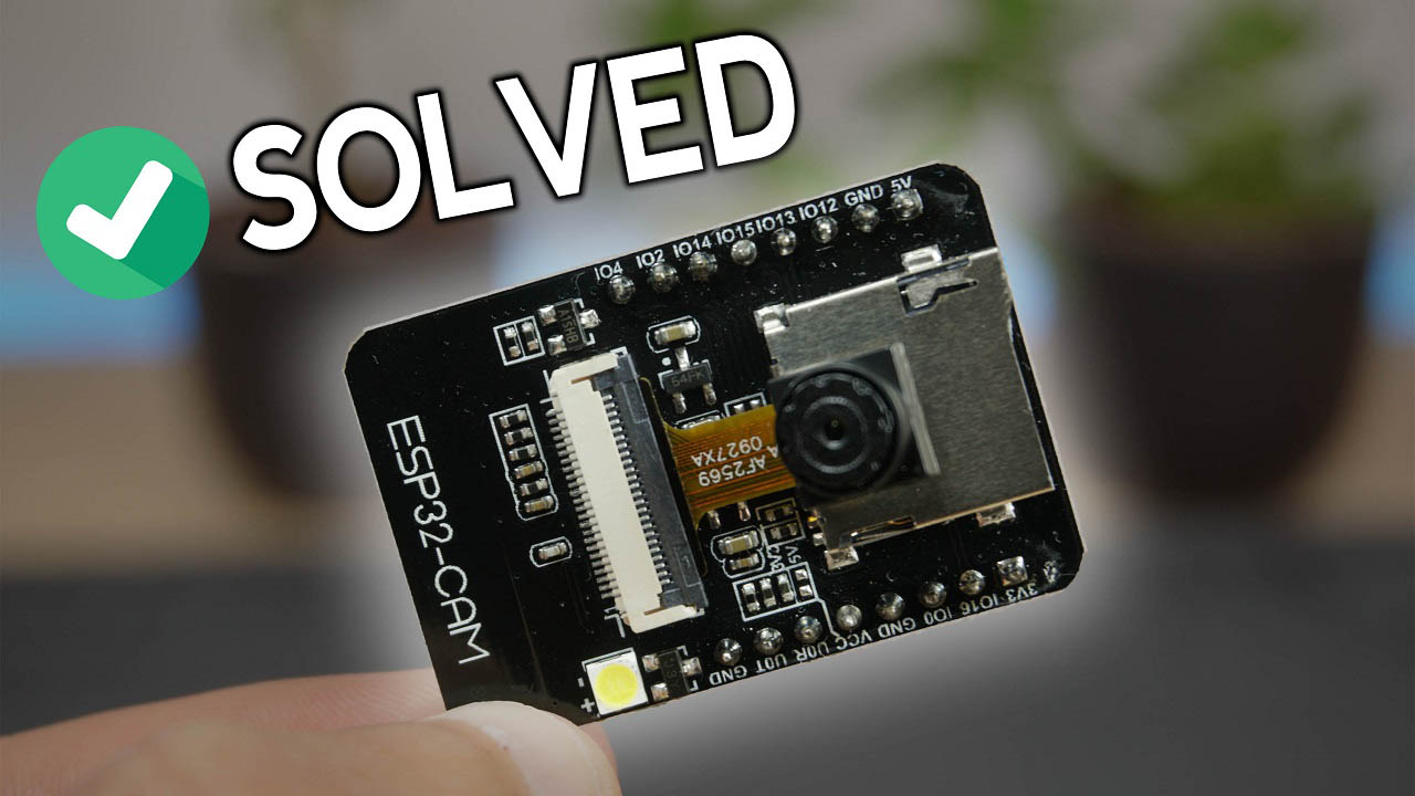
ESP32-CAM Troubleshooting Guide: Most Common Problems Fixed
This guide is a compilation with the most common errors when using the ESP32-CAM and how to fix them. The ESP32-CAM can be a bit tricky to setup, follow this guide.
- Suitable forB.Tech/Diploma IoT/ESP32 students
- Build time1-2 weeks
- LevelIntermediate
- Available atAjvika Labs, Kakinada
About this project
After releasing some projects with the
ESP32-CAM
, some readers reported issues when trying to use the ESP32-CAM. This guide is a compilation with the most common errors when using the ESP32-CAM and how to fix them.
We’ve released the following projects with the
ESP32-CAM
:
Video Streaming, Face Detection and Face Recognition
ESP32 IP CAM – Video Streaming (Home Assistant and Node-RED)
Take Photo and Save to MicroSD Card
PIR Motion Detector with Photo Capture
Take Photo, Save to SPIFFS and Display in Web Server
Note:
some of our readers reported errors when trying to follow the
ESP32-CAM project with Home Assistant
. We’ve modified some lines on the code, so most of the problems related with that project should be fixed.
Please note that we couldn’t reproduce some of the errors on our end. However, we’ve gathered all the information given by our readers to get answers to the most common issues.
If you have a different problem or a different solution to these issues, you can share your tips by writing a comment below.
Most common errors:
Failed to connect to ESP32: Timed out waiting for packet header
Camera init failed with error 0x20001 or similar
Brownout detector or Guru meditation error
Sketch too big error – Wrong partition scheme selected
Board at COMX is not available – COM Port Not Selected
Psram error: GPIO isr service is not installed
Weak Wi-Fi Signal
No IP Address in Arduino IDE Serial Monitor
Can’t open web server
The image lags/shows lots of latency
esp_camera_fb_get(): Failed to get the frame on time!
1. Failed to connect to ESP32: Timed out waiting for packet header
This error means that the ESP32-CAM is not in flashing mode or it is not connected properly to the FTDI programmer.
Double-check the steps to upload code
Double-check that you’ve followed the exact steps to put your ESP32-CAM in flashing mode. Failing to complete one of the steps may result in that error. Here’s the steps you need to follow:
Connect the ESP32-CAM board to your computer using an FTDI programmer. Follow the next schematic diagram:
Important:
GPIO 0
needs to be connected to
GND
so that you’re able to upload code.
Many FTDI programmers have a jumper that allows you to select 3.3V or 5V. Make sure the jumper is in the right place to select 5V.
Important:
GPIO 0 needs to be connected to GND so that you’re able to upload code.
ESP32-CAM
FTDI Programmer
GND
GND
5V
VCC (5V)
U0R
TX
U0T
RX
GPIO 0
GND
To upload the code, follow the next steps:
1) Go to
Tools
>
Board
and select
AI-Thinker ESP32-CAM
2) Go to
Tools
>
Port
and select the COM port the ESP32 is connected to.
3) Then, click the upload button to upload the code.
4) When you start to see these dots on the debugging window as shown below, press the ESP32-CAM on-board RST button.
After a few seconds, the code should be successfully uploaded to your board.
GPIO 0 must be connected to GND
Important:
if you can’t upload the code, double-check that
GPIO 0
is connected to
GND
and that you selected the right settings in the
Tools
menu. You should also press the on-board Reset button to restart your ESP32 in flashing mode. Also, check that you have the FTDI programmer jumper cap set to 5V.
Check the FTDI programmer you are using
One of our readers reported the following: “
found out that you can program the board with a USB-to-TTL module model CP2102 and that the CH340 model does NOT work
“.
This is the FTDI programmer we’re using
Power the ESP32-CAM with 5V
Some of our readers reported that they could only upload code when the ESP32 was powered with 5V. So, power the ESP32-CAM with 5V.
FTDI Programmer 5V
Measure the output voltage of your
FTDI programmer
(VCC and GND) using a
Multimeter
to ensure it’s providing 5V to your ESP32-CAM.
2. Camera init failed with error 0x20001 or similar
If you get this exact error, it means that your camera OVX is not connected properly to your ESP32 board or you have the wrong pin assignment in the code.
Sometimes, unplugging and plugging the FTDI programmer multiple times or restart the board multiple times, might solve the issue.
Camera not connected properly
The camera has a tiny connector and you must ensure it’s connected in the the right away and with a secure fit, otherwise it will fail to establish a connection.
Wrong pin assignment in the code
When you get this error, it might also mean that you didn’t select the right board in the define section or the pin definition is wrong for your board.
Make sure you select the right camera module in your projects. You just need to uncomment the right camera module and comment all the others:
//#define CAMERA_MODEL_WROVER_KIT
//#define CAMERA_MODEL_M5STACK_PSRAM
#define CAMERA_MODEL_AI_THINKER
In this example, we’re using the CAMERA_MODEL_AI_THINKER, so it’s the one that is enabled. Otherwise, it will fail the pin assignment and the camera will fail to init.
There are many esp32-cam boards being released (“fake boards”) that the wiring between the ESP32 and the OV camera might be different, so selecting the camera module, might not be enough. You might need to check each gpio declaration with your board pinout.
For example, M5Stack board
without
PSRAM has a different pin assignment than the M5STACK
with
PSRAM (defined on the code by default). So, you need to change the pin definition in the code accordingly to the board pinout.
Not enough power through USB source
If you’re powering your ESP32 through a USB port on your computer, it might not be supplying enough power.
Faulty FTDI programmer
Some readers also reported this problem was solved by replacing their actual FTDI programmer
with this one
The camera/connector is broken
If you get this error, it might also mean that your camera or the camera ribbon is broken. If that is the case, you may get a new OV2640 camera probe.
3. Brownout detector or Guru meditation error
When you open your Arduino IDE Serial monitor and the error message “Brownout detector was triggered” is constantly being printed over and over again. It means that there’s some sort of hardware problem.
It’s often related to one of the following issues:
Poor quality USB cable;
USB cable is too long;
Board with some defect (bad solder joints);
Bad computer USB port;
Or not enough power provided by the computer USB port.
Solution:
try a different shorter USB cable (with data wires)
use a different computer USB port or use a USB hub with an external power supply
some readers reported that when powering the ESP32-CAM with 5V, the issue was fixed.
Also, follow the suggestions described in issue 2.
4. Sketch too big error – Wrong partition scheme selected
When you get the following error:
Sketch too big; see http://www.arduino.cc/en/Guide/Troubleshooting#size for tips on reducing it.
Error compiling for board ESP32 Dev Module.
It means that you haven’t selected the right partition scheme. Make sure you select the right partition scheme. In your Arduino IDE, go to
Tools
>
Partition Scheme
, select “
Huge APP (3MB No OTA)
“.
5. Board at COMX is not available – COM Port Not Selected
If you get the following error or similar:
serial.serialutil. SerialException: could not open port 'COM8': WindowsError(2, 'The system cannot find the file specified.')
Failed to execute script esptool
the selected serial port Failed to execute script esptool
does not exist or your board is not connected
Board at COM8 is not available
It means that you haven’t selected the COM port in the Tools menu. In your Arduino IDE, go to
Tools
>
Port
and select the COM port the ESP32 is connected to.
It might also mean that the ESP32-CAM is not establishing a serial connection with your computer or it is not properly connected to the USB connector.
6. Psram error: GPIO isr service is not installed
You are using a board without PSRAM and you get the following error or similar:
E (161) gpio: gpio_isr_handler_remove(380): GPIO isr service is not installed, call gpio_install_isr_service() first
Camera
ESP32-CAM
, some readers reported issues when trying to use the ESP32-CAM. This guide is a compilation with the most common errors when using the ESP32-CAM and how to fix them.
We’ve released the following projects with the
ESP32-CAM
:
Video Streaming, Face Detection and Face Recognition
ESP32 IP CAM – Video Streaming (Home Assistant and Node-RED)
Take Photo and Save to MicroSD Card
PIR Motion Detector with Photo Capture
Take Photo, Save to SPIFFS and Display in Web Server
Note:
some of our readers reported errors when trying to follow the
ESP32-CAM project with Home Assistant
. We’ve modified some lines on the code, so most of the problems related with that project should be fixed.
Please note that we couldn’t reproduce some of the errors on our end. However, we’ve gathered all the information given by our readers to get answers to the most common issues.
If you have a different problem or a different solution to these issues, you can share your tips by writing a comment below.
Most common errors:
Failed to connect to ESP32: Timed out waiting for packet header
Camera init failed with error 0x20001 or similar
Brownout detector or Guru meditation error
Sketch too big error – Wrong partition scheme selected
Board at COMX is not available – COM Port Not Selected
Psram error: GPIO isr service is not installed
Weak Wi-Fi Signal
No IP Address in Arduino IDE Serial Monitor
Can’t open web server
The image lags/shows lots of latency
esp_camera_fb_get(): Failed to get the frame on time!
1. Failed to connect to ESP32: Timed out waiting for packet header
This error means that the ESP32-CAM is not in flashing mode or it is not connected properly to the FTDI programmer.
Double-check the steps to upload code
Double-check that you’ve followed the exact steps to put your ESP32-CAM in flashing mode. Failing to complete one of the steps may result in that error. Here’s the steps you need to follow:
Connect the ESP32-CAM board to your computer using an FTDI programmer. Follow the next schematic diagram:
Important:
GPIO 0
needs to be connected to
GND
so that you’re able to upload code.
Many FTDI programmers have a jumper that allows you to select 3.3V or 5V. Make sure the jumper is in the right place to select 5V.
Important:
GPIO 0 needs to be connected to GND so that you’re able to upload code.
ESP32-CAM
FTDI Programmer
GND
GND
5V
VCC (5V)
U0R
TX
U0T
RX
GPIO 0
GND
To upload the code, follow the next steps:
1) Go to
Tools
>
Board
and select
AI-Thinker ESP32-CAM
2) Go to
Tools
>
Port
and select the COM port the ESP32 is connected to.
3) Then, click the upload button to upload the code.
4) When you start to see these dots on the debugging window as shown below, press the ESP32-CAM on-board RST button.
After a few seconds, the code should be successfully uploaded to your board.
GPIO 0 must be connected to GND
Important:
if you can’t upload the code, double-check that
GPIO 0
is connected to
GND
and that you selected the right settings in the
Tools
menu. You should also press the on-board Reset button to restart your ESP32 in flashing mode. Also, check that you have the FTDI programmer jumper cap set to 5V.
Check the FTDI programmer you are using
One of our readers reported the following: “
found out that you can program the board with a USB-to-TTL module model CP2102 and that the CH340 model does NOT work
“.
This is the FTDI programmer we’re using
Power the ESP32-CAM with 5V
Some of our readers reported that they could only upload code when the ESP32 was powered with 5V. So, power the ESP32-CAM with 5V.
FTDI Programmer 5V
Measure the output voltage of your
FTDI programmer
(VCC and GND) using a
Multimeter
to ensure it’s providing 5V to your ESP32-CAM.
2. Camera init failed with error 0x20001 or similar
If you get this exact error, it means that your camera OVX is not connected properly to your ESP32 board or you have the wrong pin assignment in the code.
Sometimes, unplugging and plugging the FTDI programmer multiple times or restart the board multiple times, might solve the issue.
Camera not connected properly
The camera has a tiny connector and you must ensure it’s connected in the the right away and with a secure fit, otherwise it will fail to establish a connection.
Wrong pin assignment in the code
When you get this error, it might also mean that you didn’t select the right board in the define section or the pin definition is wrong for your board.
Make sure you select the right camera module in your projects. You just need to uncomment the right camera module and comment all the others:
//#define CAMERA_MODEL_WROVER_KIT
//#define CAMERA_MODEL_M5STACK_PSRAM
#define CAMERA_MODEL_AI_THINKER
In this example, we’re using the CAMERA_MODEL_AI_THINKER, so it’s the one that is enabled. Otherwise, it will fail the pin assignment and the camera will fail to init.
There are many esp32-cam boards being released (“fake boards”) that the wiring between the ESP32 and the OV camera might be different, so selecting the camera module, might not be enough. You might need to check each gpio declaration with your board pinout.
For example, M5Stack board
without
PSRAM has a different pin assignment than the M5STACK
with
PSRAM (defined on the code by default). So, you need to change the pin definition in the code accordingly to the board pinout.
Not enough power through USB source
If you’re powering your ESP32 through a USB port on your computer, it might not be supplying enough power.
Faulty FTDI programmer
Some readers also reported this problem was solved by replacing their actual FTDI programmer
with this one
The camera/connector is broken
If you get this error, it might also mean that your camera or the camera ribbon is broken. If that is the case, you may get a new OV2640 camera probe.
3. Brownout detector or Guru meditation error
When you open your Arduino IDE Serial monitor and the error message “Brownout detector was triggered” is constantly being printed over and over again. It means that there’s some sort of hardware problem.
It’s often related to one of the following issues:
Poor quality USB cable;
USB cable is too long;
Board with some defect (bad solder joints);
Bad computer USB port;
Or not enough power provided by the computer USB port.
Solution:
try a different shorter USB cable (with data wires)
use a different computer USB port or use a USB hub with an external power supply
some readers reported that when powering the ESP32-CAM with 5V, the issue was fixed.
Also, follow the suggestions described in issue 2.
4. Sketch too big error – Wrong partition scheme selected
When you get the following error:
Sketch too big; see http://www.arduino.cc/en/Guide/Troubleshooting#size for tips on reducing it.
Error compiling for board ESP32 Dev Module.
It means that you haven’t selected the right partition scheme. Make sure you select the right partition scheme. In your Arduino IDE, go to
Tools
>
Partition Scheme
, select “
Huge APP (3MB No OTA)
“.
5. Board at COMX is not available – COM Port Not Selected
If you get the following error or similar:
serial.serialutil. SerialException: could not open port 'COM8': WindowsError(2, 'The system cannot find the file specified.')
Failed to execute script esptool
the selected serial port Failed to execute script esptool
does not exist or your board is not connected
Board at COM8 is not available
It means that you haven’t selected the COM port in the Tools menu. In your Arduino IDE, go to
Tools
>
Port
and select the COM port the ESP32 is connected to.
It might also mean that the ESP32-CAM is not establishing a serial connection with your computer or it is not properly connected to the USB connector.
6. Psram error: GPIO isr service is not installed
You are using a board without PSRAM and you get the following error or similar:
E (161) gpio: gpio_isr_handler_remove(380): GPIO isr service is not installed, call gpio_install_isr_service() first
Camera
Technologies used
Hardware components
- ESP32
- ESP32-CAM
- Arduino
- PIR
- SD Card
Software & tools
- Arduino IDE
- Node-RED
- Home Assistant
What you get
- Working project / hardware kit, tested before delivery
- Complete source code with explanation
- Project demo and guidance for your viva
- Project report, PPT and IEEE paper support (on request)
Delivery & Payment
Delivery takes a minimum of two weeks from the date your inquiry is confirmed.
Payment is in two parts:
• 50% advance to start the project
• Remaining 50% before delivery
Note:
• Documentation and PPT are not included by default
• If you need documentation/PPT, it can be arranged for extra time and cost
We'll confirm the exact timeline and cost with you after reviewing your requirements.
Related IoT/ESP32 projects

IoT/ESP32
ESP32 External Wake Up from Deep Sleep
This article shows how to put the ESP32 in deep sleep mode and wake it with an external wake up like a button press. We'll cover how to use...
View project
IoT/ESP32
ESP32: Upload Files to LittleFS using Arduino IDE
Upload files to the ESP32 Filesystem (LittleFS) by using a plugin for Arduino IDE (1.8.X). The plugin lets you use three different filesyste...
View project
IoT/ESP32
ESP32: Guide for MicroSD Card Module using Arduino IDE
Use a microSD card with the ESP32: you'll learn how to read and write files to the microSD card. To interface a microSD card with an ESP32 b...
View project
IoT/ESP32
ESP32 Save Data Permanently using Preferences Library
Save data permanently on the ESP32 flash memory using Preferences.h library. The data held in the flash memory persists across resets or pow...
View project