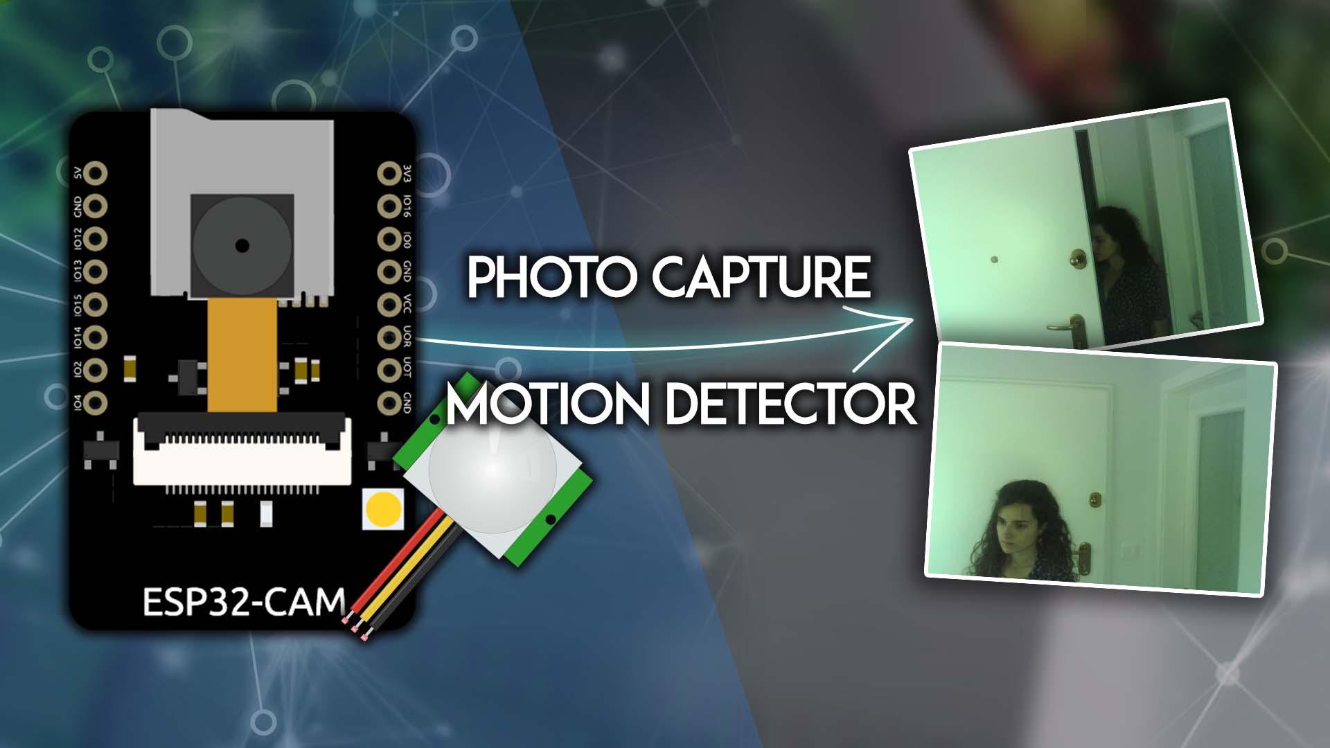
ESP32-CAM PIR Motion Detector with Photo Capture (saves to microSD card)
In this project, we're going to make a motion sensor detector with photo capture using an ESP32-CAM. When your PIR sensor detects motion, it wakes up, takes a photo and saves it in the microSD card.
- Suitable forB.Tech/Diploma IoT/ESP32 students
- Build time1-2 weeks
- LevelIntermediate
- Available atAjvika Labs, Kakinada
About this project
This project
is very similar to a previous one
, but after many requests, we added a PIR motion sensor to the circuit. So, when motion is detected a picture is taken and saved on the microSD card.
Other ESP32-CAM projects and tutorials:
ESP32-CAM Video Streaming with Arduino IDE
ESP32-CAM Take Photo and Save to MicroSD Card
Take Photo, Save to SPIFFS and Display in Web Server
ESP32-CAM Troubleshooting Guide
We have a similar project using a Raspberry Pi and a camera module:
Raspberry Pi Motion Detector with Photo Capture
Parts Required
For this project, you’ll need the following parts:
ESP32-CAM with OV2640
– read
Best ESP32-CAM Dev Boards
MicroSD card
PIR motion sensor
FTDI programmer
Female-to-female jumper wires
5V power supply for ESP32-CAM
or power bank (optional)
You can use the preceding links or go directly to
MakerAdvisor.com/tools
to find all the parts for your projects at the best price!
Project Overview
Here is a quick overview of how the project works.
The ESP32-CAM is in
deep sleep mode with external wake up
enabled.
When motion is detected, the
PIR motion sensor
sends a signal to wake up the ESP32.
The ESP32-CAM takes a photo and saves it on the microSD card.
It goes back to deep sleep mode until a new signal from the PIR motion sensor is received.
Recommended reading:
ESP32 Deep Sleep with Arduino IDE and Wake Up Sources
Prerequisites
Before proceeding, make sure you check the following prerequisites.
Formatting the MicroSD Card
The first thing we recommend doing is formatting your microSD card. You can use the Windows formatter tool or any other microSD formatter software.
1.
Insert the microSD card into your computer. Go to
My Computer
and right-click on the SD card. Select
Format
as shown in the figure below.
2.
A new window pops up. Select
FAT32
, press
Start
to initialize the formatting process and follow the onscreen instructions.
Note:
according to the product specifications, the ESP32-CAM should only support 4 GB SD cards. However, we’ve tested with 16 GB SD card and it works well.
Installing the ESP32 Boards in Arduino IDE
We’ll program the ESP32 board using Arduino IDE. So, you need the Arduino IDE installed as well as the ESP32 boards. Follow the next tutorial if you haven’t already.
Installing the ESP32 Board in Arduino IDE (Windows, Mac OS X, Linux)
Deep Sleep with External Wake Up
In this project, the ESP32-CAM will be in deep sleep mode, and it will wake up with an external wake-up source (the PIR motion sensor sends a HIGH signal when it detects motion).
Only RCT GPIOs can be used as a wake-up source. The ESP32 RTC GPIOs are: 0, 2, 4, 12, 13, 14, 15, 25, 26, 27, 32, 33,34, 35, 36, and 39.
Let’s recap the ESP32-CAM pinout.
GPIO 4
GPIO 2
GPIO 14
GPIO 15
GPIO 13,
and
GPIO 12
are all used by the microSD card. But, if we use the microSD card in 1-bit mode, we can free up GPIOs 12, and 13. That’s what we’re going to do: we’ll use the microSD card in 1-bit mode and GPIO 13 to connect to the PIR motion sensor.
ESP32-CAM Take Photo with PIR Motion Sensor – Code
Copy the following code to your Arduino IDE.
/*********
IMPORTANT!!!
- Select Board \"AI Thinker ESP32-CAM\"
- GPIO 0 must be connected to GND to upload a sketch
- After connecting GPIO 0 to GND, press the ESP32-CAM on-board RESET button to put your board in flashing mode
Permission is hereby granted, free of charge, to any person obtaining a copy of this software and associated documentation files.
The above copyright notice and this permission notice shall be included in all copies or substantial portions of the Software.
*********/
#include \"esp_camera.h\"
#include \"Arduino.h\"
#include \"FS.h\" // SD Card ESP32
#include \"SD_MMC.h\" // SD Card ESP32
#include \"soc/soc.h\" // Disable brownout problems
#include \"soc/rtc_cntl_reg.h\" // Disable brownout problems
#include \"driver/rtc_io.h\"
#include `EEPROM.h` // read and write from flash memory
// define the number of bytes you want to access
#define EEPROM_SIZE 1
RTC_DATA_ATTR int bootCount = 0;
// Pin definition for CAMERA_MODEL_AI_THINKER
#define PWDN_GPIO_NUM 32
#define RESET_GPIO_NUM -1
#define XCLK_GPIO_NUM 0
#define SIOD_GPIO_NUM 26
#define SIOC_GPIO_NUM 27
#define Y9_GPIO_NUM 35
#define Y8_GPIO_NUM 34
#define Y7_GPIO_NUM 39
#define Y6_GPIO_NUM 36
#define Y5_GPIO_NUM 21
#define Y4_GPIO_NUM 19
#define Y3_GPIO_NUM 18
#define Y2_GPIO_NUM 5
#define VSYNC_GPIO_NUM 25
#define HREF_GPIO_NUM 23
#define PCLK_GPIO_NUM 22
int pictureNumber = 0;
void setup() {
WRITE_PERI_REG(RTC_CNTL_BROWN_OUT_REG, 0); //disable brownout detector
Serial.begin(115200);
Serial.setDebugOutput(true);
camera_config_t config;
config.ledc_channel = LEDC_CHANNEL_0;
config.ledc_timer = LEDC_TIMER_0;
config.pin_d0 = Y2_GPIO_NUM;
config.pin_d1 = Y3_GPIO_NUM;
config.pin_d2 = Y4_GPIO_NUM;
config.pin_d3 = Y5_GPIO_NUM;
config.pin_d4 = Y6_GPIO_NUM;
config.pin_d5 = Y7_GPIO_NUM;
config.pin_d6 = Y8_GPIO_NUM;
config.pin_d7 = Y9_GPIO_NUM;
config.pin_xclk = XCLK_GPIO_NUM;
config.pin_pclk = PCLK_GPIO_NUM;
config.pin_vsync = VSYNC_GPIO_NUM;
config.pin_href = HREF_GPIO_NUM;
config.pin_sccb_sda = SIOD_GPIO_NUM;
config.pin_sccb_scl = SIOC_GPIO_NUM;
config.pin_pwdn = PWDN_GPIO_NUM;
config.pin_reset = RESET_GPIO_NUM;
config.xclk_freq_hz = 20000000;
config.pixel_format = PIXFORMAT_JPEG;
config.grab_mode = CAMERA_GRAB_LATEST;
pinMode(4, INPUT);
digitalWrite(4, LOW);
rtc_gpio_hold_dis(GPIO_NUM_4);
if(psramFound()){
config.frame_size = FRAMESIZE_UXGA; // FRAMESIZE_ + QVGA|CIF|VGA|SVGA|XGA|SXGA|UXGA
config.jpeg_quality = 10;
config.fb_count = 2;
} else {
config.frame_size = FRAMESIZE_SVGA;
config.jpeg_quality = 12;
config.fb_count = 1;
}
// Init Camera
esp_err_t err = esp_camera_init(&config);
if (err != ESP_OK) {
Serial.printf(\"Camera init failed with error 0x%x\", err);
return;
}
Serial.println(\"Starting SD Card\");
delay(500);
if (!SD_MMC.begin(\"/sdcard\", true)) { // true enables 1-bit mode to free up GPIOs
Serial.println(\"SD Card Mount Failed\");
//return;
}
uint8_t cardType = SD_MMC.cardType();
if(cardType == CARD_NONE){
Serial.println(\"No SD Card attached\");
return;
}
camera_fb_t * fb = NULL;
// Take Picture with Camera
fb = esp_camera_fb_get();
if(!fb) {
Serial.println(\"Camera capture failed\");
return;
}
// initialize EEPROM with predefined size
EEPROM.begin(EEPROM_SIZE);
pictureNumber = EEPROM.read(0) + 1;
// Path where new picture will be saved in SD Card
String path = \"/picture\" + String(pictureNumber) +\".jpg\";
fs::FS &fs = SD_MMC;
Serial.printf(\"Picture file name: %s\
\", path.c_str());
File file = fs.open(path.c_str(), FILE_WRITE);
if(!file){
Serial.println(\"Failed to open file in writing mode\");
}
else {
file.write(fb->buf, fb->len); // payload (image), payload length
Serial.printf(\"Saved file to path: %s\
\", path.c_str());
EEPROM.write(0, pictureNumber);
EEPROM.commit();
}
file.close();
esp_camera_fb_return(fb);
delay(1000);
// Turns off the ESP32-CAM white on-board LED (flash) connected to GPIO 4
pinMode(4, OUTPUT);
digitalWrite(4, LOW);
rtc_gpio_hold_en(GPIO_NUM_4);
esp_sleep_enable_ext0_wakeup(GPIO_NUM_13, 1);
rtc_gpio_
Technologies used
Hardware components
- ESP32
- ESP32-CAM
- Arduino
- Raspberry Pi
- PIR
- IR Sensor
- SD Card
Software & tools
- Arduino IDE
What you get
- Working project / hardware kit, tested before delivery
- Complete source code with explanation
- Project demo and guidance for your viva
- Project report, PPT and IEEE paper support (on request)
Related IoT/ESP32 projects

ESP32 External Wake Up from Deep Sleep
This article shows how to put the ESP32 in deep sleep mode and wake it with an external wake up like a button press. We'll cover how to use...
View project
ESP32: Upload Files to LittleFS using Arduino IDE
Upload files to the ESP32 Filesystem (LittleFS) by using a plugin for Arduino IDE (1.8.X). The plugin lets you use three different filesyste...
View project
ESP32: Guide for MicroSD Card Module using Arduino IDE
Use a microSD card with the ESP32: you'll learn how to read and write files to the microSD card. To interface a microSD card with an ESP32 b...
View project
ESP32 Save Data Permanently using Preferences Library
Save data permanently on the ESP32 flash memory using Preferences.h library. The data held in the flash memory persists across resets or pow...
View project