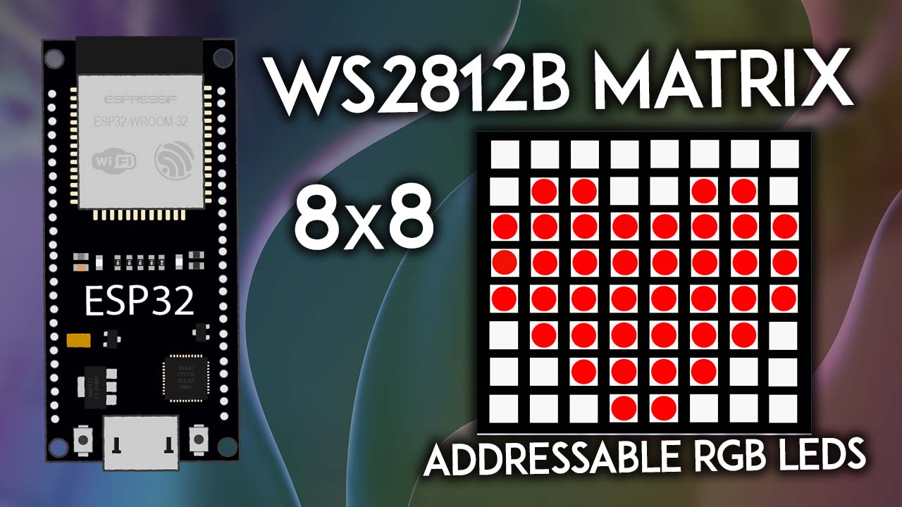
ESP32: 64 WS2812B RGB LED 8×8 Matrix (Arduino IDE)
Use the 64 WS2812B RGB LED 8x8 matrix panel with ESP32 using Arduino IDE. Control each LED, set different colors/brightness, draw shapes/icons and create a rainbow RGB effect.
- Suitable forB.Tech/Diploma IoT/ESP32 students
- Build time1-2 weeks
- LevelBeginner
- Available atAjvika Labs, Kakinada
About this project
This guide shows how to use the 64 WS2812B RGB LED 8×8 matrix panel with the ESP32 using Arduino IDE. We’ll show you how to control each LED, set different colors/brightness, draw shapes/icons, and create a rainbow RGB effect.
We also have a dedicated guide that shows how to use the
WS2812B Addressable RGB LEDs (Neopixels) with the ESP32 board using Arduino IDE
Prerequisites
Before proceeding, make sure you have the Arduino IDE installed and the ESP32 boards. Follow the next tutorial if you haven’t already:
Installing ESP32 Board in Arduino IDE 2 (Windows, Mac OS X, Linux)
Introducing 64 WS2812B RGB LED 8×8 Matrix Panel (Neopixels)
The
WS2812B 8×8 Matrix Panel has 64 RGB LEDs
(also known as neopixels) that allow you to control each LED independently with any color and brightness using just one digital pin of your ESP32.
Powering the WS2812B LED 8×8 Matrix Panel
The LED matrix panel should be powered using a 5V power source. At 5V, each LED draws about 50mA when set to its full brightness. This means that at full brightness in white for every 30 LEDs, the matrix panel may draw as much as 1.5A. Make sure you select a power source that matches your needs. An AC to DC power adapter that provides 5V and 2A should do the job:
5V 2A power adapter
If you use an external power source, don’t forget to connect the power source ground to the ESP32 GND pin. In this tutorial, we’ll control 64 LEDs (it’s a square matrix 8×8) using an external power source.
Parts Required
For this project, you need the following parts:
ESP32 board
– any model of your choice
8×8 64 LED Matrix Panel with WS2812B
5V 2A power adapter
Jumper wires
You can use the preceding links or go directly to
MakerAdvisor.com/tools
to find all the parts for your projects at the best price!
Wiring 64 WS2812B RGB LED 8×8 Matrix to the ESP32
Wiring the WS2812B to the ESP32 is quite simple, as it only requires one digital pin (
DIN
) to control each LED individually.
8×8 Matrix
ESP32
V-
GND
DIN
Any digital pin (for example:
GPIO 2
)*
Power Adapter
GND
ESP32
GND
GND
8×8 Matrix
V-
5V
8×8 Matrix
V+
* you can use any other suitable GPIOs. Check the ESP32 Pinout Guide:
ESP32 Pinout Reference: Which GPIO pins should you use?
ESP32-S3 DevKitC Pinout Reference Guide: GPIOs Explained
Wiring the 8×8 matrix panel to the ESP32 is very simple. We’ll share the wiring diagram below with an external power adapter, but you can also use the 5V directly from the ESP32 if you
are not using
white color with full brightness.
If you’re using a power adapter, connect
GND
to
V-
, and connect
GPIO 2
to the
DIN
(data) pin. Then, wire the external power adapter
5V
to the
V+
and
GND
to
V-
Installing the FastLED Library
There are several libraries to interface the WS2812B LEDs with the ESP32. We’ll use the
FastLED
library. You can install it quickly by following these steps:
Open the Arduino IDE Library Manager
FastLED
Install the FastLED library by
Daniel Garcia
Example #1 – ESP32 Control WS2812B 8×8 Matrix Panel RGB LEDs Individually
The following code sets a different color for each WS2812B RGB LED in the matrix using (X, Y) coordinates. Upload the following code to your board, and it will work straight away.
/*
Permission is hereby granted, free of charge, to any person obtaining a copy of this software and associated documentation files.
The above copyright notice and this permission notice shall be included in all copies or substantial portions of the Software.
*/
#include `FastLED.h`
#define DIN_PIN 2
#define MATRIX_WIDTH 8
#define MATRIX_HEIGHT 8
#define NUM_LEDS (MATRIX_WIDTH * MATRIX_HEIGHT)
#define BRIGHTNESS 80 // Brightness (0-255)
#define LED_TYPE WS2812B
#define COLOR_ORDER GRB
#define ZIGZAG true // Set false if your panel is wired in straight rows instead of zigzag
#define DELAY_MS 500
CRGB leds[NUM_LEDS];
// Convert (x,y) coordinates to the corresponding index in the matrix
uint16_t coordToIndex(uint8_t x, uint8_t y) {
if (ZIGZAG && (y & 0x01)) {
x = (MATRIX_WIDTH - 1) - x;
}
return (y * MATRIX_WIDTH) + x;
}
// Set the color of a pixel at (x,y)
void setPixel(uint8_t x, uint8_t y, uint8_t r, uint8_t g, uint8_t b, uint8_t brightness = 255) {
if (x >= MATRIX_WIDTH || y >= MATRIX_HEIGHT)
return;
CRGB color = CRGB(r, g, b);
color.nscale8(brightness);
leds[coordToIndex(x, y)] = color;
}
void setup() {
FastLED.addLeds<LED_TYPE, DIN_PIN, COLOR_ORDER>(leds, NUM_LEDS);
FastLED.setBrightness(BRIGHTNESS);
FastLED.clear();
}
void loop() {
setPixel(0, 0, 255, 0, 0); // First LED x=0 and y=0 | Red - Full brightness
FastLED.show();
delay(DELAY_MS);
setPixel(3, 3, 0, 255, 0, 128); // LED x=3 and y=3 | Green - 50% brightness
FastLED.show();
delay(DELAY_MS);
setPixel(7, 7, 0, 0, 255, 200); // Last LED x=7 and y=7 | Blue - ~78% brightness
FastLED.show();
delay(DELAY_MS);
FastLED.clear(); // All LEDs off
FastLED.show();
delay(DELAY_MS);
}
How Does the Code Work?
Let’s take a quick look at the code to see how this first example works.
Including Library
First, you need to include the
FastLED.h
library, which is required to control the WS2812B LEDs.
#include `FastLED.h`
Global Variables
The matrix panel data in pin (
DIN_PIN
) is connected to the ESP32
GPIO 2
#define DIN_PIN 2
Define the matrix width and matrix height, then multiple those two values to calculate the total number of LEDs.
#define MATRIX_WIDTH 8
#define MATRIX_HEIGHT 8
#define NUM_LEDS (MATRIX_WIDTH * MATRIX_HEIGHT)
Set the brightness of all LEDs (range is from 0 to 255).
#define BRIGHTNESS 80
Define the LED type
WS2812B
and set the Color Order to
GRB
. Most WS2812B LEDs use GRB order, not RGB.
#define LED_TYPE WS2812B
#define COLOR_ORDER GRB
The
ZIGZAG
variable is used in the
coordToIndex()
function to assign the correct LED position depending on whether the LEDs are wired in a zigzag or if all the matrix rows are wired in the same direction.
#define ZIGZAG true
Delay time for the animation in milliseconds (500ms = 0.5s).
#define DELAY_MS 500
Create an array called
leds
that holds all colors for the 8 LEDs. CRGB is FastLED’s color type definition (Red, Green, Blue).
CRGB leds[NUM_LEDS];
coordToIndex()
The
coordToIndex()
function converts the (x, y) coordinates to the corresponding index in the matrix:
uint16_t coordToIndex(uint8_t x, uint8_t y) {
if (ZIGZAG && (y & 0x01)) {
x = (MATRIX_WIDTH - 1) - x;
}
return (y * MATRIX_WIDTH) + x;
}
setPixel()
The
setPixel()
function sets the color and brightness of a single pixel on the LED matrix. First, it checks if the coordinates are correct, then builds a CRGB color from the supplied color values (red, green, blue), scales that color’s intensity by the brightness parameter (from 0 to 255), and finally writes the correct color into the global
leds
array at the index returned by the
coordToIndex()
function.
void setPixel(uint8_t x, uint8_t y, uint8_t r, uint8_t g, uint8_t b, uint8_t brightness = 255) {
if (x >= MATRIX_WIDTH || y >= MATRIX_HEIGHT)
return;
CRGB color = CRGB(r, g, b);
color.nscale8(brightness);
leds[coordToIndex(x, y)] = color;
}
If you have an LED matrix in zigzag you refer to the coordinates of each LED as follows:
setup()
In the
setup()
, start by initializing the LED strip or ring using the FastLED library. You need to pass the arguments:
LED Type = WS2812B
Data Pin =
DIN_PIN
Color Order = GRB (Most WS2812B LEDs use GRB order, not RGB)
FastLED.addLeds<LED_TYPE, DIN_PIN, COLOR_ORDER>(leds, NUM_LEDS);
Set the global brightness level and turn off all LEDs at the start.
FastLED.setBrightness(BRIGHTNESS);
FastLED.clear();
loop()
The
loop()
runs continously. It fir
We also have a dedicated guide that shows how to use the
WS2812B Addressable RGB LEDs (Neopixels) with the ESP32 board using Arduino IDE
Prerequisites
Before proceeding, make sure you have the Arduino IDE installed and the ESP32 boards. Follow the next tutorial if you haven’t already:
Installing ESP32 Board in Arduino IDE 2 (Windows, Mac OS X, Linux)
Introducing 64 WS2812B RGB LED 8×8 Matrix Panel (Neopixels)
The
WS2812B 8×8 Matrix Panel has 64 RGB LEDs
(also known as neopixels) that allow you to control each LED independently with any color and brightness using just one digital pin of your ESP32.
Powering the WS2812B LED 8×8 Matrix Panel
The LED matrix panel should be powered using a 5V power source. At 5V, each LED draws about 50mA when set to its full brightness. This means that at full brightness in white for every 30 LEDs, the matrix panel may draw as much as 1.5A. Make sure you select a power source that matches your needs. An AC to DC power adapter that provides 5V and 2A should do the job:
5V 2A power adapter
If you use an external power source, don’t forget to connect the power source ground to the ESP32 GND pin. In this tutorial, we’ll control 64 LEDs (it’s a square matrix 8×8) using an external power source.
Parts Required
For this project, you need the following parts:
ESP32 board
– any model of your choice
8×8 64 LED Matrix Panel with WS2812B
5V 2A power adapter
Jumper wires
You can use the preceding links or go directly to
MakerAdvisor.com/tools
to find all the parts for your projects at the best price!
Wiring 64 WS2812B RGB LED 8×8 Matrix to the ESP32
Wiring the WS2812B to the ESP32 is quite simple, as it only requires one digital pin (
DIN
) to control each LED individually.
8×8 Matrix
ESP32
V-
GND
DIN
Any digital pin (for example:
GPIO 2
)*
Power Adapter
GND
ESP32
GND
GND
8×8 Matrix
V-
5V
8×8 Matrix
V+
* you can use any other suitable GPIOs. Check the ESP32 Pinout Guide:
ESP32 Pinout Reference: Which GPIO pins should you use?
ESP32-S3 DevKitC Pinout Reference Guide: GPIOs Explained
Wiring the 8×8 matrix panel to the ESP32 is very simple. We’ll share the wiring diagram below with an external power adapter, but you can also use the 5V directly from the ESP32 if you
are not using
white color with full brightness.
If you’re using a power adapter, connect
GND
to
V-
, and connect
GPIO 2
to the
DIN
(data) pin. Then, wire the external power adapter
5V
to the
V+
and
GND
to
V-
Installing the FastLED Library
There are several libraries to interface the WS2812B LEDs with the ESP32. We’ll use the
FastLED
library. You can install it quickly by following these steps:
Open the Arduino IDE Library Manager
FastLED
Install the FastLED library by
Daniel Garcia
Example #1 – ESP32 Control WS2812B 8×8 Matrix Panel RGB LEDs Individually
The following code sets a different color for each WS2812B RGB LED in the matrix using (X, Y) coordinates. Upload the following code to your board, and it will work straight away.
/*
Permission is hereby granted, free of charge, to any person obtaining a copy of this software and associated documentation files.
The above copyright notice and this permission notice shall be included in all copies or substantial portions of the Software.
*/
#include `FastLED.h`
#define DIN_PIN 2
#define MATRIX_WIDTH 8
#define MATRIX_HEIGHT 8
#define NUM_LEDS (MATRIX_WIDTH * MATRIX_HEIGHT)
#define BRIGHTNESS 80 // Brightness (0-255)
#define LED_TYPE WS2812B
#define COLOR_ORDER GRB
#define ZIGZAG true // Set false if your panel is wired in straight rows instead of zigzag
#define DELAY_MS 500
CRGB leds[NUM_LEDS];
// Convert (x,y) coordinates to the corresponding index in the matrix
uint16_t coordToIndex(uint8_t x, uint8_t y) {
if (ZIGZAG && (y & 0x01)) {
x = (MATRIX_WIDTH - 1) - x;
}
return (y * MATRIX_WIDTH) + x;
}
// Set the color of a pixel at (x,y)
void setPixel(uint8_t x, uint8_t y, uint8_t r, uint8_t g, uint8_t b, uint8_t brightness = 255) {
if (x >= MATRIX_WIDTH || y >= MATRIX_HEIGHT)
return;
CRGB color = CRGB(r, g, b);
color.nscale8(brightness);
leds[coordToIndex(x, y)] = color;
}
void setup() {
FastLED.addLeds<LED_TYPE, DIN_PIN, COLOR_ORDER>(leds, NUM_LEDS);
FastLED.setBrightness(BRIGHTNESS);
FastLED.clear();
}
void loop() {
setPixel(0, 0, 255, 0, 0); // First LED x=0 and y=0 | Red - Full brightness
FastLED.show();
delay(DELAY_MS);
setPixel(3, 3, 0, 255, 0, 128); // LED x=3 and y=3 | Green - 50% brightness
FastLED.show();
delay(DELAY_MS);
setPixel(7, 7, 0, 0, 255, 200); // Last LED x=7 and y=7 | Blue - ~78% brightness
FastLED.show();
delay(DELAY_MS);
FastLED.clear(); // All LEDs off
FastLED.show();
delay(DELAY_MS);
}
How Does the Code Work?
Let’s take a quick look at the code to see how this first example works.
Including Library
First, you need to include the
FastLED.h
library, which is required to control the WS2812B LEDs.
#include `FastLED.h`
Global Variables
The matrix panel data in pin (
DIN_PIN
) is connected to the ESP32
GPIO 2
#define DIN_PIN 2
Define the matrix width and matrix height, then multiple those two values to calculate the total number of LEDs.
#define MATRIX_WIDTH 8
#define MATRIX_HEIGHT 8
#define NUM_LEDS (MATRIX_WIDTH * MATRIX_HEIGHT)
Set the brightness of all LEDs (range is from 0 to 255).
#define BRIGHTNESS 80
Define the LED type
WS2812B
and set the Color Order to
GRB
. Most WS2812B LEDs use GRB order, not RGB.
#define LED_TYPE WS2812B
#define COLOR_ORDER GRB
The
ZIGZAG
variable is used in the
coordToIndex()
function to assign the correct LED position depending on whether the LEDs are wired in a zigzag or if all the matrix rows are wired in the same direction.
#define ZIGZAG true
Delay time for the animation in milliseconds (500ms = 0.5s).
#define DELAY_MS 500
Create an array called
leds
that holds all colors for the 8 LEDs. CRGB is FastLED’s color type definition (Red, Green, Blue).
CRGB leds[NUM_LEDS];
coordToIndex()
The
coordToIndex()
function converts the (x, y) coordinates to the corresponding index in the matrix:
uint16_t coordToIndex(uint8_t x, uint8_t y) {
if (ZIGZAG && (y & 0x01)) {
x = (MATRIX_WIDTH - 1) - x;
}
return (y * MATRIX_WIDTH) + x;
}
setPixel()
The
setPixel()
function sets the color and brightness of a single pixel on the LED matrix. First, it checks if the coordinates are correct, then builds a CRGB color from the supplied color values (red, green, blue), scales that color’s intensity by the brightness parameter (from 0 to 255), and finally writes the correct color into the global
leds
array at the index returned by the
coordToIndex()
function.
void setPixel(uint8_t x, uint8_t y, uint8_t r, uint8_t g, uint8_t b, uint8_t brightness = 255) {
if (x >= MATRIX_WIDTH || y >= MATRIX_HEIGHT)
return;
CRGB color = CRGB(r, g, b);
color.nscale8(brightness);
leds[coordToIndex(x, y)] = color;
}
If you have an LED matrix in zigzag you refer to the coordinates of each LED as follows:
setup()
In the
setup()
, start by initializing the LED strip or ring using the FastLED library. You need to pass the arguments:
LED Type = WS2812B
Data Pin =
DIN_PIN
Color Order = GRB (Most WS2812B LEDs use GRB order, not RGB)
FastLED.addLeds<LED_TYPE, DIN_PIN, COLOR_ORDER>(leds, NUM_LEDS);
Set the global brightness level and turn off all LEDs at the start.
FastLED.setBrightness(BRIGHTNESS);
FastLED.clear();
loop()
The
loop()
runs continously. It fir
Technologies used
Hardware components
- ESP32
- Arduino
- NeoPixel
Software & tools
- Arduino IDE
What you get
- Working project / hardware kit, tested before delivery
- Complete source code with explanation
- Project demo and guidance for your viva
- Project report, PPT and IEEE paper support (on request)
Delivery & Payment
Delivery takes a minimum of two weeks from the date your inquiry is confirmed.
Payment is in two parts:
• 50% advance to start the project
• Remaining 50% before delivery
Note:
• Documentation and PPT are not included by default
• If you need documentation/PPT, it can be arranged for extra time and cost
We'll confirm the exact timeline and cost with you after reviewing your requirements.
Related IoT/ESP32 projects

IoT/ESP32
ESP32 External Wake Up from Deep Sleep
This article shows how to put the ESP32 in deep sleep mode and wake it with an external wake up like a button press. We'll cover how to use...
View project
IoT/ESP32
ESP32: Upload Files to LittleFS using Arduino IDE
Upload files to the ESP32 Filesystem (LittleFS) by using a plugin for Arduino IDE (1.8.X). The plugin lets you use three different filesyste...
View project
IoT/ESP32
ESP32: Guide for MicroSD Card Module using Arduino IDE
Use a microSD card with the ESP32: you'll learn how to read and write files to the microSD card. To interface a microSD card with an ESP32 b...
View project
IoT/ESP32
ESP32 Save Data Permanently using Preferences Library
Save data permanently on the ESP32 flash memory using Preferences.h library. The data held in the flash memory persists across resets or pow...
View project