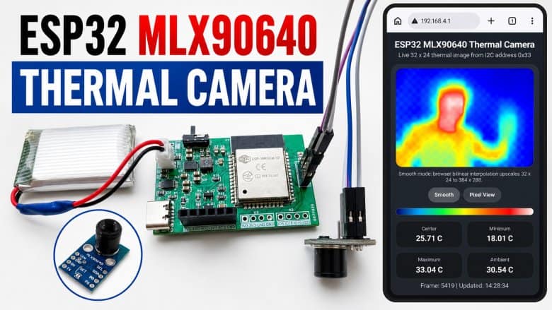
DIY ESP32 MLX90640 IR Thermal Camera with Live Web Display
Build an ESP32 thermal camera with MLX90640 IR image array temperature sensor & Wi-Fi webserver with C++ code for real-time thermal imaging
- Suitable forB.Tech/Diploma ESP32/IoT students
- Build time1-2 weeks
- LevelBeginner
- Available atAjvika Labs, Kakinada
About this project
Overview
In this project, we will develop an
ESP32 Thermal Imaging Camera
using the
MLX90640 IR Image Array Temperature Sensor
. The MLX90640 is a far-infrared thermal sensor with a
32 × 24 pixel array
, providing
768 individual temperature measurement points
for thermal image generation.
Compared to lower-resolution thermal sensors such as the
AMG8833
, which has only an
8 × 8 pixel array
with 64 thermal detectors, the MLX90640 offers significantly better thermal image detail. Its higher pixel density allows the camera to detect heat patterns from objects, electronic components, human hands, faces, and surrounding temperature variations more clearly.
The project uses an
ESP32 module
as the main controller and the MLX90640 sensor as the thermal imaging element. The thermal data is processed as a
32 × 24 infrared temperature matrix
and converted into a smooth thermal heatmap for visualization. The web interface includes enhanced thermal image processing features such as
bilinear interpolation, color palette mapping, frame smoothing, contrast enhancement, and hot/cold temperature markers
. It also displays useful real-time values, including minimum temperature, maximum temperature, average temperature, and center temperature.
This
DIY ESP32 MLX90640 Thermal Imaging Camera
is useful for heat detection, electronics troubleshooting, human presence detection, temperature visualization, thermal monitoring, and IoT-based infrared imaging applications.
MLX90640 32×24 IR Array Temperature Sensor
The
MLX90640
from
Melexis
is a small size, non-contact, and low cost
far-infrared thermal sensor
array that integrates
768 (32×24)
thermal sensors into a compact and standard 4-lead TO39 package.
This sensor is capable of capturing detailed
thermal images
by measuring the infrared radiation emitted by objects in its field of view, translating it into temperature readings ranging from
-40°C
to
300°C
Different MLX90640 Breakout Boards
The sensor achieves a high
degree of accuracy
, maintaining approximately
±1°C
across its operational range. Furthermore, the
MLX90640
includes additional functionalities like an ambient temperature sensor and a supply voltage sensor, enhancing its precision and reliability. Data from the
IR sensors
, as well as the ambient and supply voltage measurements, are stored in
internal RAM
and can be accessed via an I2C interface.
The
MLX90640 thermal camera
features a
32×24 array
, totaling 768 individual far-infrared pixels. Each pixel captures temperature data, allowing for detailed
thermal imaging
and accurate temperature measurements across the sensor’s field of view.
The MLX90640 is not only functional but also user-friendly, tailored for hobbyists and professionals alike. It supports both
3.3V
and
5V
operating voltages and communicates through a configurable
I2C interface
that can reach data rates up to
1MHz
. This sensor is compatible with platforms like Arduino, Raspberry Pi, or STM32.
The sensor’s capability to adjust the frame rate from
0.5
to
64Hz
allows users to fine-tune its performance based on specific application requirements, whether it’s tracking fast-moving objects or conducting detailed thermal evaluations over a slower period. Refer to
MLX90640 Datasheet
for more information about this Thermal Camera.
Features and Benefits
Small size, low cost 32×24 pixels IR array
Easy to integrate
Industry standard four lead TO39 package
Factory calibrated
Noise Equivalent Temperature Difference (NETD): 0.1K RMS @1Hz refresh rate
I2C compatible digital interface
Programmable refresh rate 0.5Hz…64Hz
3.3V supply voltage
Current consumption is less than 23mA
2 FOV options – 55°x35° and 110°x75°
Operating temperature -40°C ÷ 85°C
Target temperature -40°C ÷ 300°C
Complies with RoHS regulations
Check previous MLX90640 Thermal Camera projects and tutorials:
1.
DIY Thermal Camera with MLX90640 & Raspberry Pi
2.
Thermal Fever Detector with MLX90640 & OpenCV
ESP32 MLX90640 Thermal Camera Circuit Design & Schematic
Let’s walk through the hardware design of the
ESP32 MLX90640 Thermal Camera
in detail.
Fig: Schematic for ESP32 MLX90640 Thermal Camera
The board is powered through a USB Type-C port. If battery operation is required, charging can be handled by a Li-ion charging IC such as the
BQ24092D
(or similar). It supports
CC/CV charging
, pre-conditioning, and auto cut-off. A small LED indicates charging status. A JST-PH connector is used to connect a
3.7 V Li-ion/LiPo battery
. A slide switch is added to turn the system on or off.
The regulated 3.3 V supply for the ESP32 and the MLX90640 sensor is provided by a
buck-boost converter
like the
TPS63020
. It ensures a stable 3.3 V output across the entire
battery voltage
range (3.0–4.2 V). This keeps the ESP32 and the Thermal Sensor powered reliably even at low battery levels.
Programming is done through the PROG header or the onboard USB interface using an
FTDI adapter
(depending on your ESP32 module). Two transistors, Q1 and Q2, handle the auto-reset and auto-boot sequence. This means no buttons are needed during code upload.
Extra GPIO pins are broken out for sensors and modules.
IO21 (SDA)
and
IO22 (SCL)
provide the I²C interface for connecting the
MLX90640 IR Thermal Image Array Temperature Sensor
, which is the core of the Thermal Camera system.
PCB Designing & Gerber Files
The schematic of the
ESP32 MLX90640 Thermal Camera
was created in
EasyEDA
, and from there it was converted into a compact PCB layout.
Fig: PCB Layout of ESP32 MLX90640 Thermal Camera
The board is designed with mostly
SMD components
to keep the size small. Resistors and capacitors are in the 0603 package, while the main ICs, such as the
TPS63020 buck-boost converter
and the
BQ24092D battery charger,
are also in SMD form.
Fig: Front Side of PCB
All of the critical components, including the ESP32-WROOM module, are placed on the
front side of the PCB
, which makes assembly easier and more reliable.
Fig: Backside of PCB
Here are the link of files that you can download for PCB manufacturing and PCB assembly services.
Download:
Schematic PDF
Download:
Bill of Materials (BOM)
Download:
Pick & Place File
Download:
Gerber File
PCB Ordering Online & Assembly
The
Gerber file
for this
ESP32 MLX90640 Thermal Camera
is provided above. You can download the Gerber file and place an order with a PCB manufacturer like
AIVON
for as low as $1 for a PCB Prototype.
To order the PCB, visit the
AIVON Official Website
and upload the Gerber file using the
Quote Now
option. You can then choose your required parameters, such as
Material Type, Dimensions, Quantity, Thickness, and Solder Mask Color.
AIVON
is making PCB prototyping and assembly more affordable for new users by offering
$1 PCB Prototype
and
$35 PCB Assembly
with Shipping fee
$30 OFF
on your first PCB order. With this promotion, you can enjoy
free shipping
on your first order and affordable assembly service for your project.
Here is the promotion link
:
AIVON PCB/PCBA Promotion Offer
Once all the details are filled in, select your country and shipping method. After confirming everything, you can place the order and wait for your boards to arrive.
Assembly & Testing the ESP32 MLX90640 PCB Board
After about a week, the finished PCBs arrived from
AIVON
. The quality was excellent, with smooth solder pads and precise silkscreen printing—perfect for assembling the ESP32 MLX90640 IoT board.
Assembly begins with soldering all the
SMD components
on the front side. The design is compact, so only the front contains the ESP32 module, buck-boost converter, charger IC, and supporting resistors and capacitors.
In the first prototype there were a few minor value adjustments for capacitors and resistors, but these have been corrected in the
final Gerber release
, so you can assemble the latest version without any issues.
Once assembled, connect a
3.7 V Li-ion/LiPo battery
to the JST connector. Programming the ESP32 is done through th
Technologies used
Hardware components
- ESP32
- Arduino
- Raspberry Pi
- STM32
- IR Sensor
Software & tools
- EasyEDA
What you get
- Working project / hardware kit, tested before delivery
- Complete source code with explanation
- Project demo and guidance for your viva
- Project report, PPT and IEEE paper support (on request)
Delivery & Payment
Delivery takes a minimum of two weeks from the date your inquiry is confirmed.
Payment is in two parts:
• 50% advance to start the project
• Remaining 50% before delivery
Note:
• Documentation and PPT are not included by default
• If you need documentation/PPT, it can be arranged for extra time and cost
We'll confirm the exact timeline and cost with you after reviewing your requirements.
Related ESP32/IoT projects

ESP32/IoT
IoT Based ECG Monitoring with AD8232 ECG Sensor & ESP32
IoT Based ECG Monitoring with AD8232 ECG Sensor & ESP32 using online IoT Cloud platform Ubidots. Interface Nodemcu ESP8266/ESP32 with AD8232...
View project
ESP32/IoT
ESP32 Fingerprint Attendance System with Live Web Dashboard
Build a fingerprint biometric attendance system using ESP32, fingerprint sensor, OLED display, and a professional web dashboard with C++ Cod...
View project
ESP32/IoT
IoT AC Energy Meter with PZEM-004T & ESP32 WebServer
IoT based AC Energy Meter with PZEM-004T & ESP32 WebServer to display Voltage, Current, Power, Energy, Frequency, Power Factor on Web page
View project
ESP32/IoT
IoT Smart Electricity Energy Meter with ESP32 & Blynk 2.0
Build an IoT-based Smart Electricity Energy Meter with ESP32 & Blynk 2.0 App & measure voltage, current, power & total energy consumed onlin...
View project