Digital Taxi Fare Meter using Arduino
In this tutorial we will make a prototype of a Digital Taxi Fare Meter using Arduino LM-393 Speed Sensor. This project calculates speed and distance travelled by the taxi’s wheel and continuously displays it on 16x2 LCD display. And based on distance travelled it generates fare amount.
- Suitable forB.Tech Embedded students
- Build time5-7 weeks
- LevelAdvanced
- Available atAjvika Labs, Kakinada
About this project
A good example for this is analog speedometer and odometer that is used in old motor bikes for measuring speed and distance travelled. They have a special parts called pinion and rack arrangement in which a cable is used to rotate speedometer’s pin when wheel is rotated. This will wear out when using for long period and also needs replacement and maintenance.
In digital meter, instead of using mechanical parts, some sensors like optical interrupter or hall sensor is used to calculate the speed and distance. This is more accurate than the analog meters and doesn’t require any maintenance for long period of time. We previously built many digital speedometer projects using different sensors:
DIY Speedometer using Arduino and Processing Android App
Digital Speedometer and Odometer Circuit using PIC Microcontroller
Speed, Distance and Angle Measurement for Mobile Robots using LM393 Sensor (H206)
Today, in this tutorial we will make a prototype of a Digital Taxi Fare Meter using Arduino. This project calculates speed and distance travelled by the taxi’s wheel and continuously displays it on 16x2 LCD display. And based on distance travelled it generates fare amount when we press push button.
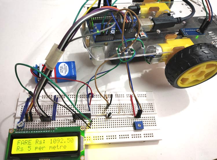
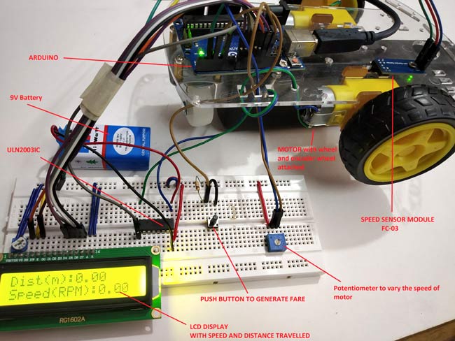
Below image shows the complete setup of Digital Taxi Meter Project
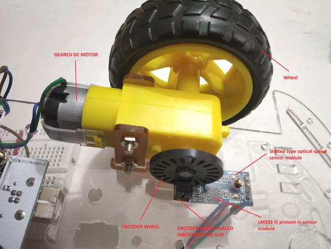
This prototype has a RC car chassis with a Speed sensor module and an encoder wheel attached to motor. Once speed is measured, we can measure the distance travelled and find the fare amount value by pressing push button. We can set the speed of the wheel using potentiometer. To learn more about using LM-393 Speed Sensor module with Arduino, follow the link. Let’s see a short introduction of Speed sensor module.
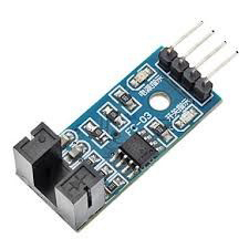
Infrared Slotted Optical LM-393 Speed Sensor Module
This is a slot type module that can be used for measuring speed of rotation of encoder wheels. This Speed sensor module works based on slot type optical interrupter also known as optical source sensor. This module requires a voltage of 3.3V to 5V and produces digital output. So it can be interfaced with any microcontroller.
The Infrared Light sensor consists consists of light source (IR-LED) and a phototransistor sensor. Both are placed with a small gap in-between them. When an object is placed in between the gap of IR LED and phototransistor it will interrupt the light beam causing phototransistor to stop passing current.
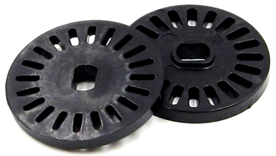
Thus with this sensor a slotted disc (Encoder Wheel) is used that can be attached to a motor and when the wheel rotates with motor it interrupts the light beam between IR LED and phototransistor that makes output On and Off (Creating Pulses).
Thus it produces HIGH output when there is interrupt between source and sensor (When any object is placed in between) and produces LOW output when there is no object placed. In the module we have an LED to indicated the optical interrupt caused.
This module comes with LM393 Comparator IC which is used to produce accurate HIGH and LOW signals at the OUTPUT. Thus this module is sometimes called as LM393 Speed sensor.
Measuring Speed and Distance Travelled to Calculate Fare
To measure the speed of rotation we need to know the number of slots present in encoder wheel. I have an encoder wheel with 20 slots in it. When they rotate one complete rotation we have 20 pulses at the output. So to calculate speed we need number of pulses produced per second.
If there are 40 pulses in one second, then
For calculating speed in RPM (Revolutions per Minute) multiply with 60.
Measuring distance travelled by the wheel is so simple. Before calculating distance, the circumference of the wheel should be known.
Where d is the diameter of the wheel.
I have a wheel (RC car wheel) of diameter 6.60 cm so the circumference is (20.7 cm).
So to calculate the distance travelled, just multiply the no of pulses detected with the circumference.
So when a wheel of Circumference 20.7cm takes 20 pulses that is one rotation of encoder wheel then the distance travelled by wheel is calculated by
In order to calculate the distance in meter divide the distance in cm value by 100.
Note: This is a small RC car wheel, in real time cars have bigger wheels than this. So I’m assuming that circumference of the wheel to be 230cm in this tutorial.
Calculating the Fare Based on Distance Travelled
To get the total fare amount, multiply the distance travelled with the fare rate (amount/meter).
Note: In this tutorial I’m assuming that Rs 5 is charged per meter.
So if the wheel is travelled 20m then fare amount will be 20*5=100 rupees.
So now let’s get the components and build the circuit.
ULN2003 Motor Driver IC
LM393 Speed Sensor Module (FC-03)
RC Smart Car Chassis with Speed encoder
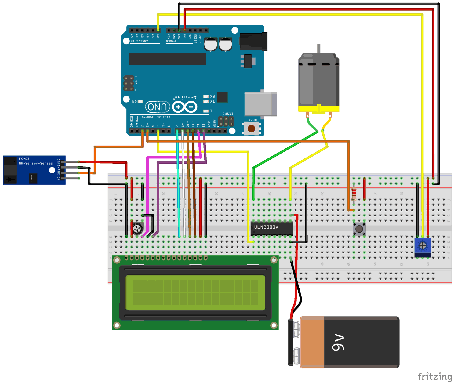
Circuit diagram for Digital Taxi Fare Meter Project using Arduino is given below:
Mounting Speed Sensor with RC Car Chassis
Speed sensor is mounted with the encoder wheel present in between the gap of sensor. In my chassis I have a special hole for placing the sensor. See the image below
Connections between Speed sensor module and Arduino
SPEED SENSOR (FC-03)
Connection between Arduino & 16x2 LCD
From potentiometer output for contrast of LCD
Learn more about interfacing LCD with Arduino here.
Connection between Arduino & ULN2003
Connection between ULN2003, DC Motor and 9v Battery
I have used a 9V battery and ULN2003 IC to externally power the motor.
Push button & Potentiometer Connection
A push button with pull down resistor is connected to the pin 3 of Arduino for generating fare amount when pressed.
Programming Arduino for Digital Taxi Meter
Complete code with a demonstration Video is given at the end of this tutorial. Here we understand few important parts of the code.
Before getting into the code we need to know about interrupts and timer One library as they are used in the code.
Interrupts is used here because we need to constantly check the output detected at the speed sensor module as the high priority. So ISR is used in the code. ISR is interrupt service routine that is called when an interrupt is occurred at the interrupt pins 2 & 3.
Arduino UNO has two interrupt pins 2 and 3.
At pin 2, output from D0 of speed sensor is connected.
At pin 3, a push button with pulldown resistor is connected.
TimerOne library is used in this code to check how many rotations (how many pulses) are detected for one second and from that we can calculate the speed per second and display them at the output. This ISR function executes for every second
So let’s see our code in detail:
1. First of all, include libraries for the functions are going to be used in programme.
2. Next declare the global variables as they will be used throughout the program.
3. Next define and initialize the LCD pins that are connected to Arduino.
4. Next in the void setup()
Technologies used
Hardware components
- Arduino
- Servo Motor
- DC Motor
- L298N
- Ultrasonic Sensor
- ESP32
Software & tools
- Arduino IDE
- ROS
- Python
- OpenCV
- VS Code
Project demo video
What you get
- Working project / hardware kit, tested before delivery
- Complete source code with explanation
- Project demo and guidance for your viva
- Project report, PPT and IEEE paper support (on request)
Related Embedded projects

ESP32 Fingerprint Attendance System with Live Web Dashboard
Build a biometric attendance system using ESP32 with AS608 fingerprint sensor that logs attendance with timestamp to web dashboard and Googl...
View project
Mars Rover Robot Replica using ESP32 CAM and Arduino
Build a Mars Rover robot replica using ESP32-CAM and Arduino with a rocker-bogie suspension system, live video streaming, and smartphone app...
View project
ESP32 CAN Bus Tutorial Interfacing MCP2515 with ESP32
Learn CAN bus communication with ESP32 and MCP2515 CAN controller to send and receive data in automotive and industrial applications.
View project
ESP32 MP3 Music Player with SD Card and I2S Amplifier
Build a standalone ESP32 MP3 music player that reads audio from SD card and outputs high-quality audio via I2S DAC amplifier with web contro...
View project