Density-Based Traffic Light Controller using Arduino
This project demonstrates a low-cost intelligent traffic signal system using Arduino and ultrasonic sensors to reduce congestion caused by fixed-timer traffic
- Suitable forB.Tech & M.Tech Embedded students
- Build time3-4 weeks
- LevelAdvanced
- Available atAjvika Labs, Kakinada
About this project
This project demonstrates a low-cost intelligent traffic signal system using Arduino and ultrasonic sensors to reduce congestion caused by fixed-timer traffic lights. Four HC-SR04 sensors detect vehicle presence in real time across four lanes. If a vehicle is detected, the lane gets a 10-second green signal; if not, the green phase is limited to 2 seconds. The two Arduino boards communicate via I2C, and RGB LEDs simulate traffic lights. The modular design improves traffic flow during uneven traffic conditions and can be easily scaled or upgraded with IoT features.
Efficient traffic management in urban areas remains a significant challenge as vehicle density grows and infrastructure struggles to keep pace. Conventional traffic lights rely on fixed timers, which often result in unnecessary delays and congestion during low-traffic periods. To address this, an intelligent traffic signal control system has been developed using low-cost, readily available components, including Arduino Uno and Arduino Nano boards and HC-SR04 ultrasonic sensors. Four ultrasonic sensors continuously monitor vehicle presence across four lanes. The sensor unit (Arduino Uno) collects proximity data and sends it via I2C communication to the control unit (Arduino Nano), which adjusts signal timing in real time.
When a vehicle is detected in a lane, that lane receives a 10-second green light. If no vehicle is present, the green phase is limited to a pre-timed 2 seconds. After the green interval, the signal automatically switches to red, and the system advances to the next lane. The distance readings from each lane are updated on the serial monitor every second.
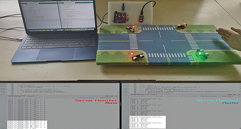
RGB LEDs indicate the traffic signal status (green/red), and the system logs its control sequence through the serial monitor. The modular, low-cost architecture enables straightforward scaling for additional lanes or future IoT enhancements. Fig. 1 presents a prototype of the system setup, and Fig. 2 provides the corresponding block diagram.
Two Arduino boards are used in the system. One functions as the sensor device and the other acts as the controller device. Both communicate over the I2C line. The sensor device detects vehicles using ultrasonic sensors, while the controller operates the RGB LED for signal indication. These components form the core of the system design. The required components are listed in Table 1 for the Bill of Materials.
Table 2 summarises the signal behaviour of the smart traffic control system based on real-time vehicle detection. It outlines how the system dynamically adjusts the durations of the green and red LED indicators based on traffic conditions in each lane.
Traffic Light Controller: Design, working, and setup
The system has been developed as a dynamic traffic signal control system using Arduino Uno and Arduino Nano, designed to operate based on real-time vehicle detection across four lanes. HC-SR04 ultrasonic sensors detect vehicle presence and RGB LEDs simulate traffic signals. Communication between the two Arduino boards is established via the I2C protocol, ensuring coordinated sensing and signal control. The setup demonstrates intelligent lane management using low-cost and widely available hardware components.
The system is divided into two functional units: the sensor unit (Arduino Uno, master) and the control unit (Arduino Nano, slave).
In the sensor unit, the Arduino Uno (master) continuously reads distance values from four ultrasonic sensors, each allocated to one lane. Vehicle presence is determined by comparing the measured distance against a fixed threshold of less than 15cm. The detection status for all four lanes is encoded into a single byte and transmitted to the control unit via I2C communication.
In the control unit, the Arduino Nano (slave) continuously receives detection data from the Uno and determines the traffic signal duration for each lane. If a vehicle is detected in a lane, the Nano activates the green LED for 10 seconds. If no vehicle is detected, the system provides a brief 2-second green phase to minimise unnecessary waiting. During this time, all other lanes remain red. The process cycles through all four lanes, dynamically optimising the signal timing in response to real-time traffic flow.
This intelligent timing approach reduces idle waiting periods at intersections and enhances traffic efficiency, particularly during uneven or fluctuating traffic conditions.
Traffic Light Controller Circuit Diagram
The complete circuit diagram of the proposed system is shown in Fig. 3. It is built around an Arduino Uno, an Arduino Nano, four ultrasonic sensors, four common-cathode RGB LEDs, and a few other supporting components. The Arduino Uno and Nano communicate through the I2C interface using pins A4 (SDA) and A5 (SCL). The controller (Arduino Nano) receives sensor data via I2C and controls the RGB LEDs accordingly to simulate the traffic signal operation.
There are two types of RGB LEDs available in market: common cathode and common anode. Their wiring differs accordingly. For a common-cathode RGB LED, the common pin is connected to GND, while for a common-anode RGB LED, it is connected to VCC. In this system, common-anode RGB LEDs have been used; therefore, the common terminal is connected to VCC. Table 3 explains the connections and functions of the various components used in the system.
Oops! This is an EFY++ article, which means it's our Premium Content. You need to be a Registered User of our website to read its complete content.
Already a registered member? If YES, then simply login to you account below. (TIP: Use 'forgot password' feature and reset and save your new password in your browser, if you forgot the last one!)
Vinayakumar February 9, 2026 At 3:16 pm I download the source code of this project at Source Code Of EFY’s DIY Projects – Electronics For You – Official Site ElectronicsForU.com. In this project two codes are used for Arduino Uno and Arduino Nano. On the website, Arduino Nano (controller) is not available. Please update. Log in to leave a comment EFY Bureau February 10, 2026 At 1:42 pm Hi, thank you for your comment. We have updated the download link. Kindly refresh the page and retry downloading. Log in to leave a comment Geetali Saha February 10, 2026 At 3:33 pm Dear Vinayakumar, True. There are supposed to be two codes-one for the Master and the other for the slave. Both codes are submitted and hence both must be available to users for download. Hope your query is resolved. Best wishes. Log in to leave a comment
I download the source code of this project at Source Code Of EFY’s DIY Projects – Electronics For You – Official Site ElectronicsForU.com. In this project two codes are used for Arduino Uno and Arduino Nano. On the website, Arduino Nano (controller) is not available. Please update.
EFY Bureau February 10, 2026 At 1:42 pm Hi, thank you for your comment. We have updated the download link. Kindly refresh the page and retry downloading. Log in to leave a comment
Hi, thank you for your comment. We have updated the download link. Kindly refresh the page and retry downloading.
Geetali Saha February 10, 2026 At 3:33 pm Dear Vinayakumar, True. There are supposed to be two codes-one for the Master and the other for the slave. Both codes are submitted and hence both must be available to users for download. Hope your query is resolved. Best wishes. Log in to leave a comment
Dear Vinayakumar, True. There are supposed to be two codes-one for the Master and the other for the slave. Both codes are submitted and hence both must be available to users for download. Hope your query is resolved. Best wishes.
SHARE YOUR THOUGHTS & COMMENTS Register or Login to leave a comment.
Smart Speed Monitoring System For Road Safety
Real-Time Face Tracking Using Raspberry Pi 4 Versus Raspberry Pi 5 With Hailo-8L
High-Voltage Capacitor Discharger
Real-time Web-based Home Automation
World’s Smallest Open-Source LoRa + GPS Module for Wearables and IoT (Only 3cm!)
Smallest Spy Video Streaming Camera
Wirelessly Control Multiple AC Appliances with Web Interface
Ultra-Low-Loss Isolated Current Sensor
STMicroelectronics has Introduced First Automotive Microcontroller With built-in AI Acceleration
Samsung Launched 200MP Image Sensor Called ISOCELL HP5
Aeva Introduced 4D LiDAR Sensor for Physical AI Systems
Blockchain Black Box For Drones
Integrated EV Drive For Higher Power Density
Hybrid Cooling System Targets Power Efficiency
Electric Field Tunes Heat Transport In Solids
DIY: Audio Signal–Controlled LED Display Using LM3914
State Reduction In Sequential Circuits
Make Your Own Musical Temperature Alarm
Buck Converter vs Linear Voltage Regulator
Ultra-Compact RGB LED For Space-Constrained Designs
Compact Varistors For High Surge Protection
Gold Plated Reed Relays For High Voltage Systems
28nm Automotive MCU For Zonal E/E Architectures
DSP / Audio Firmware Engineer (Intern) At Chordy.ai In Bengaluru
JOB: System Engineer At General Electric In Chennai
JOB: Analog Layout Engineer At Accenture In Bengaluru
JOB: HVDC HMI Engineer At Quest Global In Bengaluru
Circuit Design Calculators for Engineers and Students
Broadside Coupled Stripline Impedance Calculator
Edge Coupled Stripline Impedance Calculator
Asymmetric Stripline Impedance Calculator
Efficient traffic management in urban areas remains a significant challenge as vehicle density grows and infrastructure struggles to keep pace. Conventional traffic lights rely on fixed timers, which often result in unnecessary delays and congestion during low-traffic periods. To address this, an intelligent traffic signal control system has been developed using low-cost, readily available components, including Arduino Uno and Arduino Nano boards and HC-SR04 ultrasonic sensors. Four ultrasonic sensors continuously monitor vehicle presence across four lanes. The sensor unit (Arduino Uno) collects proximity data and sends it via I2C communication to the control unit (Arduino Nano), which adjusts signal timing in real time.
When a vehicle is detected in a lane, that lane receives a 10-second green light. If no vehicle is present, the green phase is limited to a pre-timed 2 seconds. After the green interval, the signal automatically switches to red, and the system advances to the next lane. The distance readings from each lane are updated on the serial monitor every second.
RGB LEDs indicate the traffic signal status (green/red), and the system logs its control sequence through the serial monitor. The modular, low-cost architecture enables straightforward scaling for additional lanes or future IoT enhancements. Fig. 1 presents a prototype of the system setup, and Fig. 2 provides the corresponding block diagram.
Two Arduino boards are used in the system. One functions as the sensor device and the other acts as the controller device. Both communicate over the I2C line. The sensor device detects vehicles using ultrasonic sensors, while the controller operates the RGB LED for signal indication. These components form the core of the system design. The required components are listed in Table 1 for the Bill of Materials.
Table 2 summarises the signal behaviour of the smart traffic control system based on real-time vehicle detection. It outlines how the system dynamically adjusts the durations of the green and red LED indicators based on traffic conditions in each lane.
Traffic Light Controller: Design, working, and setup
The system has been developed as a dynamic traffic signal control system using Arduino Uno and Arduino Nano, designed to operate based on real-time vehicle detection across four lanes. HC-SR04 ultrasonic sensors detect vehicle presence and RGB LEDs simulate traffic signals. Communication between the two Arduino boards is established via the I2C protocol, ensuring coordinated sensing and signal control. The setup demonstrates intelligent lane management using low-cost and widely available hardware components.
The system is divided into two functional units: the sensor unit (Arduino Uno, master) and the control unit (Arduino Nano, slave).
In the sensor unit, the Arduino Uno (master) continuously reads distance values from four ultrasonic sensors, each allocated to one lane. Vehicle presence is determined by comparing the measured distance against a fixed threshold of less than 15cm. The detection status for all four lanes is encoded into a single byte and transmitted to the control unit via I2C communication.
In the control unit, the Arduino Nano (slave) continuously receives detection data from the Uno and determines the traffic signal duration for each lane. If a vehicle is detected in a lane, the Nano activates the green LED for 10 seconds. If no vehicle is detected, the system provides a brief 2-second green phase to minimise unnecessary waiting. During this time, all other lanes remain red. The process cycles through all four lanes, dynamically optimising the signal timing in response to real-time traffic flow.
This intelligent timing approach reduces idle waiting periods at intersections and enhances traffic efficiency, particularly during uneven or fluctuating traffic conditions.
Traffic Light Controller Circuit Diagram
The complete circuit diagram of the proposed system is shown in Fig. 3. It is built around an Arduino Uno, an Arduino Nano, four ultrasonic sensors, four common-cathode RGB LEDs, and a few other supporting components. The Arduino Uno and Nano communicate through the I2C interface using pins A4 (SDA) and A5 (SCL). The controller (Arduino Nano) receives sensor data via I2C and controls the RGB LEDs accordingly to simulate the traffic signal operation.
There are two types of RGB LEDs available in market: common cathode and common anode. Their wiring differs accordingly. For a common-cathode RGB LED, the common pin is connected to GND, while for a common-anode RGB LED, it is connected to VCC. In this system, common-anode RGB LEDs have been used; therefore, the common terminal is connected to VCC. Table 3 explains the connections and functions of the various components used in the system.
Oops! This is an EFY++ article, which means it's our Premium Content. You need to be a Registered User of our website to read its complete content.
Already a registered member? If YES, then simply login to you account below. (TIP: Use 'forgot password' feature and reset and save your new password in your browser, if you forgot the last one!)
Vinayakumar February 9, 2026 At 3:16 pm I download the source code of this project at Source Code Of EFY’s DIY Projects – Electronics For You – Official Site ElectronicsForU.com. In this project two codes are used for Arduino Uno and Arduino Nano. On the website, Arduino Nano (controller) is not available. Please update. Log in to leave a comment EFY Bureau February 10, 2026 At 1:42 pm Hi, thank you for your comment. We have updated the download link. Kindly refresh the page and retry downloading. Log in to leave a comment Geetali Saha February 10, 2026 At 3:33 pm Dear Vinayakumar, True. There are supposed to be two codes-one for the Master and the other for the slave. Both codes are submitted and hence both must be available to users for download. Hope your query is resolved. Best wishes. Log in to leave a comment
I download the source code of this project at Source Code Of EFY’s DIY Projects – Electronics For You – Official Site ElectronicsForU.com. In this project two codes are used for Arduino Uno and Arduino Nano. On the website, Arduino Nano (controller) is not available. Please update.
EFY Bureau February 10, 2026 At 1:42 pm Hi, thank you for your comment. We have updated the download link. Kindly refresh the page and retry downloading. Log in to leave a comment
Hi, thank you for your comment. We have updated the download link. Kindly refresh the page and retry downloading.
Geetali Saha February 10, 2026 At 3:33 pm Dear Vinayakumar, True. There are supposed to be two codes-one for the Master and the other for the slave. Both codes are submitted and hence both must be available to users for download. Hope your query is resolved. Best wishes. Log in to leave a comment
Dear Vinayakumar, True. There are supposed to be two codes-one for the Master and the other for the slave. Both codes are submitted and hence both must be available to users for download. Hope your query is resolved. Best wishes.
SHARE YOUR THOUGHTS & COMMENTS Register or Login to leave a comment.
Smart Speed Monitoring System For Road Safety
Real-Time Face Tracking Using Raspberry Pi 4 Versus Raspberry Pi 5 With Hailo-8L
High-Voltage Capacitor Discharger
Real-time Web-based Home Automation
World’s Smallest Open-Source LoRa + GPS Module for Wearables and IoT (Only 3cm!)
Smallest Spy Video Streaming Camera
Wirelessly Control Multiple AC Appliances with Web Interface
Ultra-Low-Loss Isolated Current Sensor
STMicroelectronics has Introduced First Automotive Microcontroller With built-in AI Acceleration
Samsung Launched 200MP Image Sensor Called ISOCELL HP5
Aeva Introduced 4D LiDAR Sensor for Physical AI Systems
Blockchain Black Box For Drones
Integrated EV Drive For Higher Power Density
Hybrid Cooling System Targets Power Efficiency
Electric Field Tunes Heat Transport In Solids
DIY: Audio Signal–Controlled LED Display Using LM3914
State Reduction In Sequential Circuits
Make Your Own Musical Temperature Alarm
Buck Converter vs Linear Voltage Regulator
Ultra-Compact RGB LED For Space-Constrained Designs
Compact Varistors For High Surge Protection
Gold Plated Reed Relays For High Voltage Systems
28nm Automotive MCU For Zonal E/E Architectures
DSP / Audio Firmware Engineer (Intern) At Chordy.ai In Bengaluru
JOB: System Engineer At General Electric In Chennai
JOB: Analog Layout Engineer At Accenture In Bengaluru
JOB: HVDC HMI Engineer At Quest Global In Bengaluru
Circuit Design Calculators for Engineers and Students
Broadside Coupled Stripline Impedance Calculator
Edge Coupled Stripline Impedance Calculator
Asymmetric Stripline Impedance Calculator
Technologies used
Hardware components
- Arduino
- Raspberry Pi
- Relay
- LED
- Switch
- Sensor
- Module
- Board
- Capacitor
- Camera
- GPS
- LoRa
- RF
Project demo video
What you get
- Working project / hardware kit, tested before delivery
- Complete source code with explanation
- Project demo and guidance for your viva
- Project report, PPT and IEEE paper support (on request)
Delivery & Payment
Delivery takes a minimum of two weeks from the date your inquiry is confirmed.
Payment is in two parts:
• 50% advance to start the project
• Remaining 50% before delivery
Note:
• Documentation and PPT are not included by default
• If you need documentation/PPT, it can be arranged for extra time and cost
We'll confirm the exact timeline and cost with you after reviewing your requirements.
Related Embedded projects

Embedded
ESP32 Fingerprint Attendance System with Live Web Dashboard
Build a biometric attendance system using ESP32 with AS608 fingerprint sensor that logs attendance with timestamp to web dashboard and Googl...
View project
Embedded
Mars Rover Robot Replica using ESP32 CAM and Arduino
Build a Mars Rover robot replica using ESP32-CAM and Arduino with a rocker-bogie suspension system, live video streaming, and smartphone app...
View project
Embedded
ESP32 CAN Bus Tutorial Interfacing MCP2515 with ESP32
Learn CAN bus communication with ESP32 and MCP2515 CAN controller to send and receive data in automotive and industrial applications.
View project
Embedded
ESP32 MP3 Music Player with SD Card and I2S Amplifier
Build a standalone ESP32 MP3 music player that reads audio from SD card and outputs high-quality audio via I2S DAC amplifier with web contro...
View project