
CM³ Centralised Mode Management Machine
CM³ (Centralised Mode Management Machine) is an ESP32-based smart home automation system featuring centralized decision logic, MQTT communication, distributed sensor nodes, and real-time adaptive mode control without cloud dependency.
- Suitable forB.Tech Embedded students
- Build time3-4 weeks
- LevelBeginner
- Available atAjvika Labs, Kakinada
About this project
The objectives of CM³ are as follows
Centralize decision making across multiple devices
Enable instant adaptation based on real-time conditions
Reduce user involvement after initial configuration
Ensure reliable operation without cloud dependency
Allow flexible mode configuration based on user needs
System Architecture Overview
CM³ is designed using a centralized intelligence with distributed sensing and actuation model. The architecture separates decision logic from physical execution, which improves scalability and maintainability.
The architecture consists of
One main control unit for global decision making
Multiple slave units for localized sensing and control
Wireless communication for inter-node coordination
Event-driven data flow instead of continuous polling
This structure allows the system to expand across rooms or zones without altering the core logic.
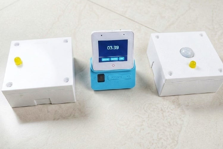
The main control unit is implemented using the ESP32 S3 Box 3. It acts as the central engine of the CM³ system.
Responsibilities of the main unit include
Maintaining the current operational mode
Processing sensor events received from slave units
Evaluating mode transition conditions
Publishing synchronized control commands
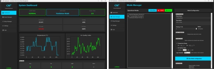
Providing a user interface for configuration
By centralising decision making, consistency is maintained across all connected devices.
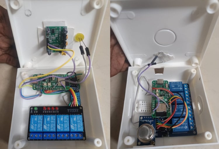
Slave units are implemented using ESP32 C3 and ESP32 C6 boards. These units form the distributed execution layer of the system.
Functions of slave units include
Interfacing with sensors
Monitoring environmental parameters
Controlling relays and connected loads
Communicating status updates to the main unit
Deploying slave units close to sensors and loads reduces wiring complexity and improves response time.
CM³ integrates multiple types of sensors to capture environmental context.
Supported sensor categories include
Motion sensors for presence detection
Temperature sensors for thermal monitoring
Humidity sensors for comfort assessment
Air quality sensors for safety and health
Sensor data is processed locally at the slave level to detect state changes. Only relevant events are transmitted to the main controller, which reduces network traffic and processing overhead.
Communication Protocol
Intercommunication between the main unit and slave units is implemented using MQTT.
Key reasons for selecting MQTT
Lightweight protocol suitable for embedded systems
Low bandwidth consumption
Decoupled communication between nodes
Mode-Based Operation
CM³ operates entirely on configurable modes rather than direct device control.
The set of active devices
The behavior of each device
Priority rules for execution
Modes are user-configurable and can be modified without changing hardware. When environmental conditions change, the system evaluates predefined logic and transitions to the appropriate mode, triggering coordinated actions across multiple devices.
Adaptive Decision Logic
CM³ uses event-driven logic instead of scheduled automation.
Decision logic characteristics include
Real-time evaluation of sensor inputs
Immediate mode transitions when conditions are met
No dependency on fixed time schedules
Minimal latency between detection and action
For example, motion detection can activate a presence mode, while prolonged inactivity can trigger an idle or power-saving mode automatically.
Reliability and Deployment Considerations
The system is designed for practical deployment.
Key reliability features include
Local processing without cloud dependency
Fast response due to on-device decision making
Modular hardware for easy expansion
Fail-safe relay control mechanisms
This ensures the system remains operational even during network outages.
CM³ transforms automation into a context-aware system that reacts naturally to user presence and environmental conditions. Users do not interact with individual devices but experience a responsive environment that adapts automatically. By prioritizing centralized intelligence and mode-based control, CM³ provides a scalable, practical, and intuitive automation solution.
ESP 32 C3 or C6 boards
temperature sensor (DHT22)
AQI sensor (MQ135 or any other)
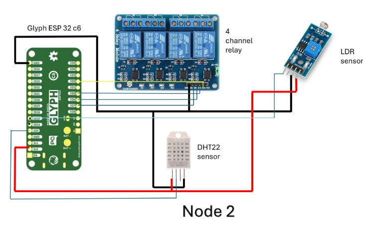
Circuit Diagram Summary (Node using ESP32-C3 / ESP32-C6)
Each node in the CM³ system is built around a Glyph ESP32 (C3 or C6) and acts as a distributed sensing and control unit. Both diagrams follow the same electrical concept; only the ESP32 variant changes.
1. Controller (ESP32-C3 / ESP32-C6) The ESP32 serves as the local processing unit for the node.
It performs three main tasks:
Controls relay outputs
Communicates with the CM³ main unit via Wi-Fi/MQTT
The ESP32 is powered using its 3.3 V pin, and all grounds are kept common to ensure signal reference stability.
2. Power Distribution
ESP32 3.3 V pin supplies the DHT22, PIR sensor, and LDR module
Relay module is powered using VCC and GND from the ESP32 side (logic power)
All components share a common ground line, which is critical for correct digital and analog readings
Technologies used
Hardware components
- ESP32
- Relay
- DHT
- LED
- Sensor
- Module
- Board
Project demo video
What you get
- Working project / hardware kit, tested before delivery
- Complete source code with explanation
- Project demo and guidance for your viva
- Project report, PPT and IEEE paper support (on request)
Related Embedded projects

ESP32 Fingerprint Attendance System with Live Web Dashboard
Build a biometric attendance system using ESP32 with AS608 fingerprint sensor that logs attendance with timestamp to web dashboard and Googl...
View project
Mars Rover Robot Replica using ESP32 CAM and Arduino
Build a Mars Rover robot replica using ESP32-CAM and Arduino with a rocker-bogie suspension system, live video streaming, and smartphone app...
View project
ESP32 CAN Bus Tutorial Interfacing MCP2515 with ESP32
Learn CAN bus communication with ESP32 and MCP2515 CAN controller to send and receive data in automotive and industrial applications.
View project
ESP32 MP3 Music Player with SD Card and I2S Amplifier
Build a standalone ESP32 MP3 music player that reads audio from SD card and outputs high-quality audio via I2S DAC amplifier with web contro...
View project