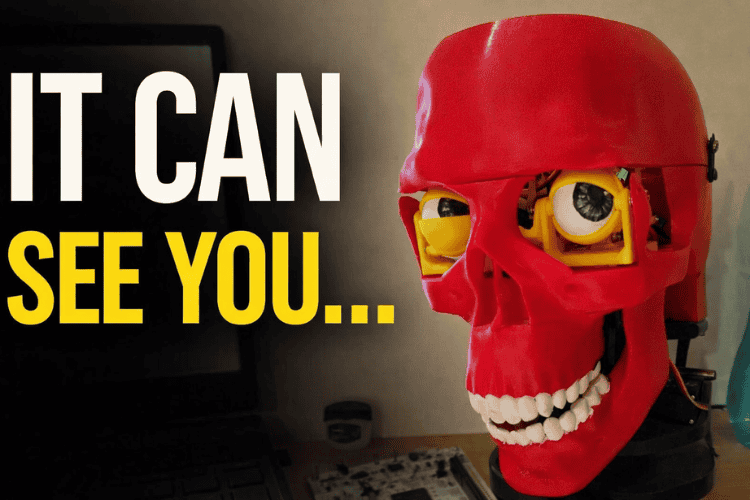
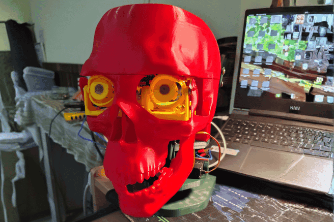
Animatronic Human-like Home assistant (Skully)
Build an AI-driven animatronic face with eye tracking, speech, and realistic motion using ESP32, servos, and vision for natural human–robot interaction.
- Suitable forM.Tech Embedded students
- Build time3-4 weeks
- LevelAdvanced
- Available atAjvika Labs, Kakinada
About this project
Technology today is rapidly transforming the way humans interact with machines, making systems more intuitive, lifelike, and intelligent. Advancements in Artificial Intelligence (AI), robotics, and embedded systems have opened new pathways for creating machines that can mimic human expression and behaviour. This project, “ AI-Driven Animatronic Face with Eye Tracking, Speech Generation, and Realistic Motion,” integrates these modern technologies to build a robotic face capable of natural interaction through movement, vision, and conversation.
In the modern world, robots are shifting from purely functional machines to interactive systems that can communicate and collaborate with humans. Whether in education, healthcare, entertainment, or research, human-like robots can make interactions more natural and engaging. Animatronic faces, in particular, help bridge the communication gap by providing visual expressiveness and emotional clarity.
Jaw movement synchronized with speech
Neck movement for natural head gestures
Modular 3D-printed components
Custom servo-driven mechanics
Educational demonstrations
Human–robot interaction research
Entertainment and animatronics
Assistive communication tools
Creative AI-powered installations
Adafruit Memento Camera Board
SMPS power supply (5v 10amps)
rasberry-pi 4 or a laptop
External Servo Supply - 5V 10A SMPS - GND tied to ESP32 GND
- GND tied to ESP32 GND
V+ → 5V (Servo Power)
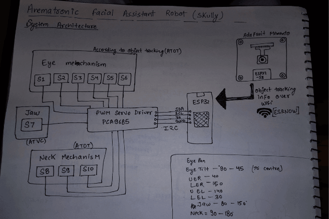
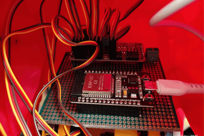
ESP32 (Main): GPIO 21 → PCA SDA GPIO 22 → PCA SCL 3.3V → PCA VCC GND → PCA GND
EYE MECHANISM (ATOT) CH0 → S1 (Eye Pan) CH1 → S2 (Eye Tilt) CH2 → S3 (Upper Eyelid Right) CH3 → S4 (Lower Eyelid Right) CH4 → S5 (Upper Eyelid Left) CH5 → S6 (Lower Eyelid Left)
CH2 → S3 (Upper Eyelid Right)
CH3 → S4 (Lower Eyelid Right)
CH4 → S5 (Upper Eyelid Left)
CH5 → S6 (Lower Eyelid Left)
NECK MECHANISM (ATOT) CH7 → S7 (Neck Tilt) CH8 → S8 (Neck Tilt) CH9 → S9 (Neck Roll)
CH7 → S7 (Neck Tilt)
CH8 → S8 (Neck Tilt)
CH9 → S9 (Neck Roll)
JAW (ATVS) CH11 → S10 (Jaw Open/Close)
CH11 → S10 (Jaw Open/Close)
JAW SYNC INPUT (USB SERIAL)
Laptop / Raspberry Pi → ESP32 over USB USB TX → ESP32 RX0 (UART0) USB RX → ESP32 TX0 (UART0) USB GND → ESP32 GND
USB TX → ESP32 RX0 (UART0)
USB RX → ESP32 TX0 (UART0)
OBJECT TRACKING NODE
Adafruit Memento ESP32-S3 CAM: OV2640 Camera Runs tracking model Sends (x, y) tracking info via ESP-NOW
Sends (x, y) tracking info via ESP-NOW
All the 3D-printed parts of the robot were first aligned and assembled using screws. Each moving section—eyes, neck, and jaw—was mounted securely so the mechanisms were stable and ready for electronics installation.
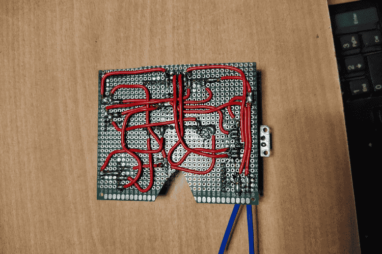
Once the mechanical assembly was complete, the circuit components were plugged in. This included connecting the ESP32, the servo controller board, and all the servos to their designated ports according to the design.
After everything was connected, all the test codes inside the test directory were run. These tests helped verify that each servo was functioning properly and that every mechanism could move through its expected range without issues.
Each servo was calibrated one by one. This involved checking its movement limits, adjusting the angles to avoid mechanical strain, and confirming smooth motion. Eye servos, neck servos, and the jaw servo were all individually calibrated to ensure accurate responses later in the system.
Once calibration was complete, the ESP32-CAM board was mounted on the robot’s forehead. The face-tracking code was then uploaded, enabling the camera to detect a person’s face and send tracking information to the main ESP32.
The main ESP32 received the tracking data from the camera and passed it to the servo controller. The controller mapped this data to the eye servos so the robot could follow the user’s face with smooth eye movement.
Finally, the speaker and microphone were installed. These components allowed the robot to listen and respond, enabling the voice assistant functionality to work alongside the animatronic movements.
Animatronic-Facial-Assistant-with-Vision-Guided-Eye-and-Jaw-Movements/ doc/ # Reference documents & servo limit charts ├── Eye Tracking/ # Vision-based eye tracking models & scripts ├── Face Tracking/ # ESP32/PlatformIO projects for head/face tracking ├── src/ # Main code: LLM agent + servo controller node ├── test/ # Hardware test sketches for servos/animations ├── LICENSE # License information └── README.md # This documentation
Camera -->|Frames| EyeTracking[Eye Tracking (DNN / Haar)] EyeTracking -->|Eye position| ServoESP[ESP32 Servo Controller]
Camera2 -->|Frames| FaceTracker[Face Tracking Node] FaceTracker -->|Coordinates| ServoESP
Mic --> STT[Speech-to-Text (Vosk)] STT --> LLM[LLM Voice Agent (Groq / Python)] LLM --> TTS[Text-to-Speech Engine] TTS --> Speaker
LLM -->|Commands| ServoESP ServoESP --> Hardware[Servos: Eye, Jaw, Neck]
## Setup Instructions
### 1. Clone the repository
``` bash git clone [email protected] :YOUR_USERNAME/Animatronic-Facial-Assistant-with-Vision-Guided-Eye-and-Jaw-Movements.git cd Animatronic-Facial-Assistant-with-Vision-Guided-Eye-and-Jaw-Movements
Face Tracking (ESP32)
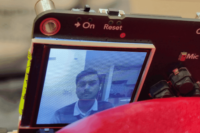
cd Face\Tracking/Platformio_memento_camera_node pio run --target upload This program turns the Adafruit MEMENTO (ESP32-S3) into a real-time face-tracking camera that also sends face coordinates wirelessly.
1. Uses the onboard camera to capture frames. 2.Runs AI-based face detection on each frame. 3.Draws a face box + center dot on the 240×240 ST7789 display. 4.Sends the face’s x/y position, width, height, and timestamp via ESP-NOW to another ESP32. 5.Repeats this continuously for live face tracking.
esp_camera.h → controls the camera hardware
human_face_detect_msr01.hpp → first-stage face detector
human_face_detect_mnp01.hpp → second-stage refinement
face_recognition_112_v1_s8.hpp → face recognition model (loaded but not actively used)
face_recognition_tool.hpp → helper tools for detection & recognition
Adafruit_GFX.h → base graphics library
Adafruit_ST7789.h → driver for the 240×240 TFT
fb_gfx.h → frame buffer utilities
esp_now.h → ESP-NOW fast P2P communication
WiFi.h → needed because ESP-NOW uses WiFi hardware
TJpg_Decoder.h → JPEG decoding (for other features)
SPI.h, Wire.h → communication buses
<vector> → C++ vector container
ra_filter.h → smoothing/filtering utility
1. Initialize Camera
2. Sets camera pins, resolution, color format, PSRAM framebuffers, etc.
3. Initialize Display
4. Turns on/wakes the ST7789 screen and prepares it for drawing.
5. Initialize ESP-NOW
6. Sets the board as WiFi station, configures peer MAC, and enables send callbacks.
Grab current camera frame
Run face detection models
Draw a green rectangle and a blue midpoint
Fill the faceData struct
If not: mark face as missing
Send data via ESP-NOW
In the modern world, robots are shifting from purely functional machines to interactive systems that can communicate and collaborate with humans. Whether in education, healthcare, entertainment, or research, human-like robots can make interactions more natural and engaging. Animatronic faces, in particular, help bridge the communication gap by providing visual expressiveness and emotional clarity.
Jaw movement synchronized with speech
Neck movement for natural head gestures
Modular 3D-printed components
Custom servo-driven mechanics
Educational demonstrations
Human–robot interaction research
Entertainment and animatronics
Assistive communication tools
Creative AI-powered installations
Adafruit Memento Camera Board
SMPS power supply (5v 10amps)
rasberry-pi 4 or a laptop
External Servo Supply - 5V 10A SMPS - GND tied to ESP32 GND
- GND tied to ESP32 GND
V+ → 5V (Servo Power)
ESP32 (Main): GPIO 21 → PCA SDA GPIO 22 → PCA SCL 3.3V → PCA VCC GND → PCA GND
EYE MECHANISM (ATOT) CH0 → S1 (Eye Pan) CH1 → S2 (Eye Tilt) CH2 → S3 (Upper Eyelid Right) CH3 → S4 (Lower Eyelid Right) CH4 → S5 (Upper Eyelid Left) CH5 → S6 (Lower Eyelid Left)
CH2 → S3 (Upper Eyelid Right)
CH3 → S4 (Lower Eyelid Right)
CH4 → S5 (Upper Eyelid Left)
CH5 → S6 (Lower Eyelid Left)
NECK MECHANISM (ATOT) CH7 → S7 (Neck Tilt) CH8 → S8 (Neck Tilt) CH9 → S9 (Neck Roll)
CH7 → S7 (Neck Tilt)
CH8 → S8 (Neck Tilt)
CH9 → S9 (Neck Roll)
JAW (ATVS) CH11 → S10 (Jaw Open/Close)
CH11 → S10 (Jaw Open/Close)
JAW SYNC INPUT (USB SERIAL)
Laptop / Raspberry Pi → ESP32 over USB USB TX → ESP32 RX0 (UART0) USB RX → ESP32 TX0 (UART0) USB GND → ESP32 GND
USB TX → ESP32 RX0 (UART0)
USB RX → ESP32 TX0 (UART0)
OBJECT TRACKING NODE
Adafruit Memento ESP32-S3 CAM: OV2640 Camera Runs tracking model Sends (x, y) tracking info via ESP-NOW
Sends (x, y) tracking info via ESP-NOW
All the 3D-printed parts of the robot were first aligned and assembled using screws. Each moving section—eyes, neck, and jaw—was mounted securely so the mechanisms were stable and ready for electronics installation.
Once the mechanical assembly was complete, the circuit components were plugged in. This included connecting the ESP32, the servo controller board, and all the servos to their designated ports according to the design.
After everything was connected, all the test codes inside the test directory were run. These tests helped verify that each servo was functioning properly and that every mechanism could move through its expected range without issues.
Each servo was calibrated one by one. This involved checking its movement limits, adjusting the angles to avoid mechanical strain, and confirming smooth motion. Eye servos, neck servos, and the jaw servo were all individually calibrated to ensure accurate responses later in the system.
Once calibration was complete, the ESP32-CAM board was mounted on the robot’s forehead. The face-tracking code was then uploaded, enabling the camera to detect a person’s face and send tracking information to the main ESP32.
The main ESP32 received the tracking data from the camera and passed it to the servo controller. The controller mapped this data to the eye servos so the robot could follow the user’s face with smooth eye movement.
Finally, the speaker and microphone were installed. These components allowed the robot to listen and respond, enabling the voice assistant functionality to work alongside the animatronic movements.
Animatronic-Facial-Assistant-with-Vision-Guided-Eye-and-Jaw-Movements/ doc/ # Reference documents & servo limit charts ├── Eye Tracking/ # Vision-based eye tracking models & scripts ├── Face Tracking/ # ESP32/PlatformIO projects for head/face tracking ├── src/ # Main code: LLM agent + servo controller node ├── test/ # Hardware test sketches for servos/animations ├── LICENSE # License information └── README.md # This documentation
Camera -->|Frames| EyeTracking[Eye Tracking (DNN / Haar)] EyeTracking -->|Eye position| ServoESP[ESP32 Servo Controller]
Camera2 -->|Frames| FaceTracker[Face Tracking Node] FaceTracker -->|Coordinates| ServoESP
Mic --> STT[Speech-to-Text (Vosk)] STT --> LLM[LLM Voice Agent (Groq / Python)] LLM --> TTS[Text-to-Speech Engine] TTS --> Speaker
LLM -->|Commands| ServoESP ServoESP --> Hardware[Servos: Eye, Jaw, Neck]
## Setup Instructions
### 1. Clone the repository
``` bash git clone [email protected] :YOUR_USERNAME/Animatronic-Facial-Assistant-with-Vision-Guided-Eye-and-Jaw-Movements.git cd Animatronic-Facial-Assistant-with-Vision-Guided-Eye-and-Jaw-Movements
Face Tracking (ESP32)
cd Face\Tracking/Platformio_memento_camera_node pio run --target upload This program turns the Adafruit MEMENTO (ESP32-S3) into a real-time face-tracking camera that also sends face coordinates wirelessly.
1. Uses the onboard camera to capture frames. 2.Runs AI-based face detection on each frame. 3.Draws a face box + center dot on the 240×240 ST7789 display. 4.Sends the face’s x/y position, width, height, and timestamp via ESP-NOW to another ESP32. 5.Repeats this continuously for live face tracking.
esp_camera.h → controls the camera hardware
human_face_detect_msr01.hpp → first-stage face detector
human_face_detect_mnp01.hpp → second-stage refinement
face_recognition_112_v1_s8.hpp → face recognition model (loaded but not actively used)
face_recognition_tool.hpp → helper tools for detection & recognition
Adafruit_GFX.h → base graphics library
Adafruit_ST7789.h → driver for the 240×240 TFT
fb_gfx.h → frame buffer utilities
esp_now.h → ESP-NOW fast P2P communication
WiFi.h → needed because ESP-NOW uses WiFi hardware
TJpg_Decoder.h → JPEG decoding (for other features)
SPI.h, Wire.h → communication buses
<vector> → C++ vector container
ra_filter.h → smoothing/filtering utility
1. Initialize Camera
2. Sets camera pins, resolution, color format, PSRAM framebuffers, etc.
3. Initialize Display
4. Turns on/wakes the ST7789 screen and prepares it for drawing.
5. Initialize ESP-NOW
6. Sets the board as WiFi station, configures peer MAC, and enables send callbacks.
Grab current camera frame
Run face detection models
Draw a green rectangle and a blue midpoint
Fill the faceData struct
If not: mark face as missing
Send data via ESP-NOW
Technologies used
Hardware components
- ESP32
- Raspberry Pi
- Servo
- LED
- Board
- Speaker
- Microphone
- Camera
Software & tools
- PlatformIO
Project demo video
What you get
- Working project / hardware kit, tested before delivery
- Complete source code with explanation
- Project demo and guidance for your viva
- Project report, PPT and IEEE paper support (on request)
Delivery & Payment
Delivery takes a minimum of two weeks from the date your inquiry is confirmed.
Payment is in two parts:
• 50% advance to start the project
• Remaining 50% before delivery
Note:
• Documentation and PPT are not included by default
• If you need documentation/PPT, it can be arranged for extra time and cost
We'll confirm the exact timeline and cost with you after reviewing your requirements.
Related Embedded projects

Embedded
ESP32 Fingerprint Attendance System with Live Web Dashboard
Build a biometric attendance system using ESP32 with AS608 fingerprint sensor that logs attendance with timestamp to web dashboard and Googl...
View project
Embedded
Mars Rover Robot Replica using ESP32 CAM and Arduino
Build a Mars Rover robot replica using ESP32-CAM and Arduino with a rocker-bogie suspension system, live video streaming, and smartphone app...
View project
Embedded
ESP32 CAN Bus Tutorial Interfacing MCP2515 with ESP32
Learn CAN bus communication with ESP32 and MCP2515 CAN controller to send and receive data in automotive and industrial applications.
View project
Embedded
ESP32 MP3 Music Player with SD Card and I2S Amplifier
Build a standalone ESP32 MP3 music player that reads audio from SD card and outputs high-quality audio via I2S DAC amplifier with web contro...
View project