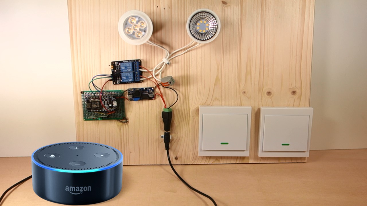
Alexa (Echo) with ESP32 and ESP8266 – Voice Controlled Relay
In this project, you're going to learn how to control the ESP8266 or the ESP32 with voice commands using Alexa (Amazon Echo Dot). As an example, we'll control two 12V lamps connected to a relay module. We'll also add two 433 MHz RF wall panel switches to physically control the lamps.
- Suitable forB.Tech/Diploma IoT/ESP32 students
- Build time1-2 weeks
- LevelIntermediate
- Available atAjvika Labs, Kakinada
About this project
Note
: this tutorial is compatible with all Echo Dot generations and with the latest fauxmoESP library (3.1.0). It works with ESP32 and ESP8266.
Watch the Project Video Demonstration
We recommend the following tutorials as a reference:
Getting Started with ESP8266 Wi-Fi Transceiver
Getting Started with ESP32 Dev Module
Decode and Send 433 MHz RF Signals with Arduino
Guide for Relay Module with Arduino
Project Overview
This project works both with ESP8266 and ESP32. We provide instructions for both development boards. Before getting straight to the project, read this section to see what you’ll achieve by the end of this project.
Control Lamps using Alexa
By the end of this project you’ll be able to control two lamps (lamp 1 and lamp 2) with voices commands using Alexa. The figure below shows a high-level overview on how the project works to control lamp 1 – it works similarly for lamp 2.
Alexa will respond to the following commands:
“Alexa, turn on lamp 1”
“Alexa, turn off lamp 1”
“Alexa, turn on lamp 2”
“Alexa, turn on lamp 2”
“Alexa, turn on lamps” turns on both lamps
“Alexa, turn off lamps” turns off both lamps
When you say something like
“Alexa, turn on lamp 1”
, the ESP8266 or ESP32 will trigger a relay to turn on lamp 1. When you say something like
“Alexa, turn off lamp 1”
, the ESP8266 or ESP32 will send a signal to the relay to turn off the lamp. This works similarly for lamp 2.
Control Lamps using 433 MHz Wall Switches
In this project, we’ll also add two 433 MHz wall switches to physically control the lamps. You’ll have a switch for each lamp. The switch changes the lamp’s state to the opposite of its current state. For example, if the lamp is off, press the wall switch to turn it on. To turn it off, you just need to press the switch again. Take a look at the figure below that illustrates how it works.
Parts Required
Here’s a complete list of the parts required for this project (click the links below to find the best price at
Maker Advisor
):
ESP Board (you can use either ESP32 or ESP8266):
ESP8266
– read
Best ESP8266 Wi-Fi Development Boards
ESP32
– we use the
ESP32 DOIT DEVKIT V1 Board – 36 GPIOs
(read
ESP32 development boards comparison
)
Alexa – Echo, Echo Show or Echo Dot
(read the next section for more details)
433 MHz RF Wall Panel Switch
433 MHz transmitter/receiver
12V 2A power adaptor
Step-down buck converter
Relay module
12V lamp
12V lamp holder
Male DC barrel jack 2.1mm
Stripboard
or
breadboard
Jumper Wires
You can use the preceding links or go directly to
MakerAdvisor.com/tools
to find all the parts for your projects at the best price!
How to Buy An Amazon Echo
You can use the links below to buy an Amazon Echo. There are several models available – all of them are compatible with this project.
Buying an Amazon Echo through Amazon is not possible for all countries. We provide links for Amazon in UK, USA, and Germany. If the Amazon Echo does not ship to your country through Amazon, you can get one from eBay (available worldwide).
Echo Dot (2nd Generation)
United States – Amazon.com
*
Available Worldwide – eBay.com
United Kingdom – Amazon.co.uk
*
Germany – Amazon.de
*
Echo (2nd Generation)
United States – Amazon.com
*
Available Worldwide – eBay.com
United Kingdom – Amazon.co.uk
*
Germany – Amazon.de
*
Echo Show
United States – Amazon.com
*
Available Worldwide – eBay.com
United Kingdom – Amazon.co.uk
*
Germany – Amazon.de
*
* We are a participant in the Amazon Services LLC Associates Program, an affiliate advertising program designed to provide a means for us to earn fees by linking to Amazon.com and affiliated sites.
433 MHz RF Wall Panel Switch
The 433 MHz RF wall panel switch is a great way to remotely control devices. It can be easily attached to a wall with adhesive tap, without the need to make holes on the walls. Additionally, it is wireless, so you don’t need to worry about wiring and then hiding cables.
In this project we’re using two wall panel switches. Instead, you can use a panel switch with two buttons – there are also another version with three switches.
This wall panel switch has a push button in its circuit, as shown in the figure below, that when pressed emits a 433 MHz signal. You can use that signal to control whatever you want. This wall panel switch uses a 27A 12V type battery (not included in the package). So, you may want to buy one, when you get your wall panel switch.
Decode the Wall Panel Switch 433 MHz RF Signals
When you press the 433 MHz wall panel switch, it sends a 433 MHz signal. You need to decode that signal using a 433 MHz receiver. To learn how to decode the 433 MHz signal read the following post:
Decode and Send 433 MHz RF Signals with Arduino
– read the “Decoder Sketch” part. The sketch works with Arduino, ESP32, and ESP8266.
Take note of the decimal (24Bit) code for each of your switches, because you’ll need them later.
In my case:
switch 1:
6819768. switch 2:
9463928. You should get different values. You’ll then use these signals in your ESP8266 or ESP32 sketch. When you press the switch, it sends a 433 MHz signal. This signal is detected by the receiver that is connected to the ESP. This way, the ESP knows the switch was pressed and it inverts the lamp’s current state.
The FauxmoESP
To control your ESP8266 or ESP32 with Amazon Echo, you need to install the FauxmoESP library. This library emulates a Belkin Wemo device, allowing you to control your ESP32 or ESP8266 using this protocol. This way, the Echo or Echo Dot instantly recognizes the device, after uploading the code, without any extra skills or third party services. You can read more about
FauxmoESP here
Installing the FauxmoESP Library
Click here to download the FauxmoESP library
. You should have a .zip folder in your Downloads
Unzip the
.zip
folder and you should get
xoseperez-fauxmoesp-50cbcf3087fd
folder
Rename your folder from
xoseperez-fauxmoesp-50cbcf3087fd
to
xoseperez_fauxmoesp
Move the xoseperez_fauxmoesp folder to your Arduino IDE installation
libraries
folder
Finally, re-open your Arduino IDE
Alexa – Echo Dot with ESP8266
Follow these next instructions if you’re using an ESP8266.
Installing the ESP8266 Board in Arduino IDE
In order to upload code to your ESP8266 using Arduino IDE, you should install an add-on for the Arduino IDE that allows you to program the ESP8266 using the Arduino IDE and its programming language. If you haven’t installed the ESP8266 add-on for the Arduino IDE, follow the next tutorial:
How to Install the ESP8266 Board in Arduino IDE
Installing the ESPAsyncTCP Library
You also need to install the ESPAsyncTCP Library library. Follow the next instructions to install it:
Click here to download the ESPAsyncTCP library
. You should have a .zip folder in your Downloads
Unzip the
.zip
folder and you should get
ESPAsyncTCP-master
folder
Rename your folder from
E
SPAsyncTCP-master
to
ESPAsyncTCP
Move the ESPAsyncTCP folder to your Arduino IDE installation
libraries
folder
Finally, re-open your Arduino IDE
Schematic
If you’re using an ESP8266 board, assemble your circuit by following the next schematic diagram – you can click the image to zoom.
If you’re having trouble following the circuit diagram, you can use the following table as a reference:
ESP8266
Connect to
GPIO 5
433 MHz receiver data pin
GPIO 4
Relay IN1 pin
GPIO 14
Relay IN2 pin
IMPORTANT NOTE
: before applying power, make sure you set your step-down buck converter output voltage to 5V! Otherwise, you may damage your ESP.
Alexa – Echo Dot with ESP32
Follow these next instructions if you’re using an ESP32.
Installing the ESP32 Board in Arduino IDE
In order to upload code to your ESP32 using Arduino IDE, you shou
Technologies used
Hardware components
- ESP32
- ESP8266
- Arduino
- Relay
Software & tools
- Arduino IDE
What you get
- Working project / hardware kit, tested before delivery
- Complete source code with explanation
- Project demo and guidance for your viva
- Project report, PPT and IEEE paper support (on request)
Related IoT/ESP32 projects

ESP32 External Wake Up from Deep Sleep
This article shows how to put the ESP32 in deep sleep mode and wake it with an external wake up like a button press. We'll cover how to use...
View project
ESP32: Upload Files to LittleFS using Arduino IDE
Upload files to the ESP32 Filesystem (LittleFS) by using a plugin for Arduino IDE (1.8.X). The plugin lets you use three different filesyste...
View project
ESP32: Guide for MicroSD Card Module using Arduino IDE
Use a microSD card with the ESP32: you'll learn how to read and write files to the microSD card. To interface a microSD card with an ESP32 b...
View project
ESP32 Save Data Permanently using Preferences Library
Save data permanently on the ESP32 flash memory using Preferences.h library. The data held in the flash memory persists across resets or pow...
View project