AI Vision Assistant Camera That Can See, Read, and Translate
This DIY AI Vision Assistant Camera captures images, performs AI-based recognition, OCR, translation, and summarisation — combining embedded hardware with cloud-based intelligence.
- Suitable forB.Tech & M.Tech Embedded students
- Build time3-4 weeks
- LevelAdvanced
- Available atAjvika Labs, Kakinada
About this project
The AI vision assistant camera is a smart device for image recognition and interpretation. Powered by AI, it analyses images from user-defined prompts and generates clear, meaningful descriptions. By combining hardware experimentation with advanced AI, the device enables hobbyists to explore vision intelligence in practical ways.
Compact yet powerful, it captures images with its onboard camera, sends them to OpenAI through API calls, and performs actions via programmable button functions. These buttons can be configured for tasks such as solving mathematical problems, translating languages, or generating image summaries. The device also supports OCR (optical character recognition), image-based translation, and other modes of information extraction.
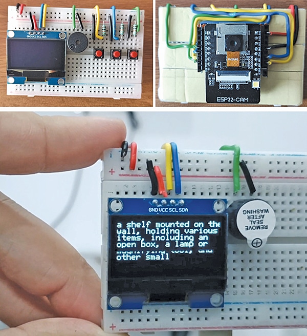
The system is centred around the ESP32-CAM module with an OV2640 camera, which serves as the primary component for capturing images. These images are processed via the OpenAI API, and the analysed results are displayed on an SSD1306 OLED screen. User interaction is facilitated through buttons that allow functions such as capturing images and triggering AI processing. Fig. 1 shows the author’s prototype, and the required components for building the device are listed in the Bill of Materials table.
Fig. 2 shows the circuit diagram of the AI vision assistant camera. The circuit uses the ESP32-CAM (U1) as the main controller for both image processing and task execution. An OLED display, HS13L03B2C01, with an I²C interface (U2) connected via SDA (IO14) and SCL (IO15) pins, is powered by 3.3V to present outputs such as text, translations, or image descriptions.
A buzzer is connected to IO4 of the ESP32-CAM, providing audio feedback or alerts during operations such as button presses or task completion. Additionally, three push buttons (SW1, SW2, SW3), each connected through a TS-1187A tactile switch with a 10kΩ pull-down resistor to 3.3V, are wired to GPIO pins IO2, IO12, and IO13. These buttons trigger different functions: SW1 for image capture/OCR, SW2 for translation or image summarisation, and SW3 for a custom AI task, such as solving mathematical problems.
The system operates with a 5V supply powering the ESP32-CAM core, while the 3.3V line supports the peripherals, including the OLED, buzzer, and push buttons.
Oops! This is an EFY++ article, which means it's our Premium Content. You need to be a Registered User of our website to read its complete content.
Already a registered member? If YES, then simply login to you account below. (TIP: Use 'forgot password' feature and reset and save your new password in your browser, if you forgot the last one!)
SHARE YOUR THOUGHTS & COMMENTS Register or Login to leave a comment.
Smart Speed Monitoring System For Road Safety
Real-Time Face Tracking Using Raspberry Pi 4 Versus Raspberry Pi 5 With Hailo-8L
High-Voltage Capacitor Discharger
Real-time Web-based Home Automation
World’s Smallest Open-Source LoRa + GPS Module for Wearables and IoT (Only 3cm!)
Smallest Spy Video Streaming Camera
Wirelessly Control Multiple AC Appliances with Web Interface
Ultra-Low-Loss Isolated Current Sensor
STMicroelectronics has Introduced First Automotive Microcontroller With built-in AI Acceleration
Samsung Launched 200MP Image Sensor Called ISOCELL HP5
Aeva Introduced 4D LiDAR Sensor for Physical AI Systems
Racetrack Shaped Resonators Enhances Light Trapping
AI Chip Uses Light Instead Of Electricity
AI Mini PC Targets Edge Computing Workloads
Battery-Free In-Tire Sensors For Autonomous Vehicles
DIY: Audio Signal–Controlled LED Display Using LM3914
State Reduction In Sequential Circuits
Make Your Own Musical Temperature Alarm
Buck Converter vs Linear Voltage Regulator
Ultra-Compact RGB LED For Space-Constrained Designs
Compact Varistors For High Surge Protection
Gold Plated Reed Relays For High Voltage Systems
28nm Automotive MCU For Zonal E/E Architectures
JOB: Technician – Repair & Testing At CTDI In Bengaluru
JOB: RFIC Analog Engineer – Clock & Timing At Texas Instruments In Bengaluru
JOB: Electronics Specialist At ABB In Bengaluru
DSP / Audio Firmware Engineer (Intern) At Chordy.ai In Bengaluru
Circuit Design Calculators for Engineers and Students
Broadside Coupled Stripline Impedance Calculator
Edge Coupled Stripline Impedance Calculator
Asymmetric Stripline Impedance Calculator
Compact yet powerful, it captures images with its onboard camera, sends them to OpenAI through API calls, and performs actions via programmable button functions. These buttons can be configured for tasks such as solving mathematical problems, translating languages, or generating image summaries. The device also supports OCR (optical character recognition), image-based translation, and other modes of information extraction.
The system is centred around the ESP32-CAM module with an OV2640 camera, which serves as the primary component for capturing images. These images are processed via the OpenAI API, and the analysed results are displayed on an SSD1306 OLED screen. User interaction is facilitated through buttons that allow functions such as capturing images and triggering AI processing. Fig. 1 shows the author’s prototype, and the required components for building the device are listed in the Bill of Materials table.
Fig. 2 shows the circuit diagram of the AI vision assistant camera. The circuit uses the ESP32-CAM (U1) as the main controller for both image processing and task execution. An OLED display, HS13L03B2C01, with an I²C interface (U2) connected via SDA (IO14) and SCL (IO15) pins, is powered by 3.3V to present outputs such as text, translations, or image descriptions.
A buzzer is connected to IO4 of the ESP32-CAM, providing audio feedback or alerts during operations such as button presses or task completion. Additionally, three push buttons (SW1, SW2, SW3), each connected through a TS-1187A tactile switch with a 10kΩ pull-down resistor to 3.3V, are wired to GPIO pins IO2, IO12, and IO13. These buttons trigger different functions: SW1 for image capture/OCR, SW2 for translation or image summarisation, and SW3 for a custom AI task, such as solving mathematical problems.
The system operates with a 5V supply powering the ESP32-CAM core, while the 3.3V line supports the peripherals, including the OLED, buzzer, and push buttons.
Oops! This is an EFY++ article, which means it's our Premium Content. You need to be a Registered User of our website to read its complete content.
Already a registered member? If YES, then simply login to you account below. (TIP: Use 'forgot password' feature and reset and save your new password in your browser, if you forgot the last one!)
SHARE YOUR THOUGHTS & COMMENTS Register or Login to leave a comment.
Smart Speed Monitoring System For Road Safety
Real-Time Face Tracking Using Raspberry Pi 4 Versus Raspberry Pi 5 With Hailo-8L
High-Voltage Capacitor Discharger
Real-time Web-based Home Automation
World’s Smallest Open-Source LoRa + GPS Module for Wearables and IoT (Only 3cm!)
Smallest Spy Video Streaming Camera
Wirelessly Control Multiple AC Appliances with Web Interface
Ultra-Low-Loss Isolated Current Sensor
STMicroelectronics has Introduced First Automotive Microcontroller With built-in AI Acceleration
Samsung Launched 200MP Image Sensor Called ISOCELL HP5
Aeva Introduced 4D LiDAR Sensor for Physical AI Systems
Racetrack Shaped Resonators Enhances Light Trapping
AI Chip Uses Light Instead Of Electricity
AI Mini PC Targets Edge Computing Workloads
Battery-Free In-Tire Sensors For Autonomous Vehicles
DIY: Audio Signal–Controlled LED Display Using LM3914
State Reduction In Sequential Circuits
Make Your Own Musical Temperature Alarm
Buck Converter vs Linear Voltage Regulator
Ultra-Compact RGB LED For Space-Constrained Designs
Compact Varistors For High Surge Protection
Gold Plated Reed Relays For High Voltage Systems
28nm Automotive MCU For Zonal E/E Architectures
JOB: Technician – Repair & Testing At CTDI In Bengaluru
JOB: RFIC Analog Engineer – Clock & Timing At Texas Instruments In Bengaluru
JOB: Electronics Specialist At ABB In Bengaluru
DSP / Audio Firmware Engineer (Intern) At Chordy.ai In Bengaluru
Circuit Design Calculators for Engineers and Students
Broadside Coupled Stripline Impedance Calculator
Edge Coupled Stripline Impedance Calculator
Asymmetric Stripline Impedance Calculator
Technologies used
Hardware components
- ESP32
- Raspberry Pi
- Relay
- MPU
- OLED
- LED
- Buzzer
- Button
- Switch
- Sensor
- Module
- Board
- Resistor
- Capacitor
- Battery
Project demo video
What you get
- Working project / hardware kit, tested before delivery
- Complete source code with explanation
- Project demo and guidance for your viva
- Project report, PPT and IEEE paper support (on request)
Delivery & Payment
Delivery takes a minimum of two weeks from the date your inquiry is confirmed.
Payment is in two parts:
• 50% advance to start the project
• Remaining 50% before delivery
Note:
• Documentation and PPT are not included by default
• If you need documentation/PPT, it can be arranged for extra time and cost
We'll confirm the exact timeline and cost with you after reviewing your requirements.
Related Embedded projects

Embedded
ESP32 Fingerprint Attendance System with Live Web Dashboard
Build a biometric attendance system using ESP32 with AS608 fingerprint sensor that logs attendance with timestamp to web dashboard and Googl...
View project
Embedded
Mars Rover Robot Replica using ESP32 CAM and Arduino
Build a Mars Rover robot replica using ESP32-CAM and Arduino with a rocker-bogie suspension system, live video streaming, and smartphone app...
View project
Embedded
ESP32 CAN Bus Tutorial Interfacing MCP2515 with ESP32
Learn CAN bus communication with ESP32 and MCP2515 CAN controller to send and receive data in automotive and industrial applications.
View project
Embedded
ESP32 MP3 Music Player with SD Card and I2S Amplifier
Build a standalone ESP32 MP3 music player that reads audio from SD card and outputs high-quality audio via I2S DAC amplifier with web contro...
View project