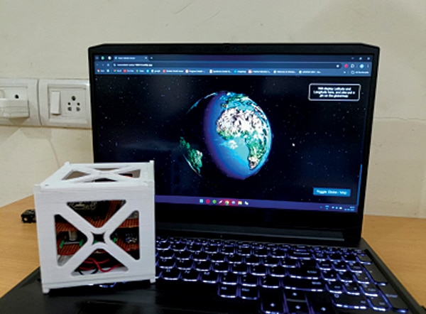
Advanced Satellite for Telemetry and Remote Access
Advanced Satellite for Telemetry and Remote Access (ASTRA) is a CubeSat model designed to offer hands-on experience in satellite technology. It serves as a
- Suitable forB.Tech & M.Tech Embedded students
- Build time3-4 weeks
- LevelAdvanced
- Available atAjvika Labs, Kakinada
About this project
Advanced Satellite for Telemetry and Remote Access (ASTRA) is a CubeSat model designed to offer hands-on experience in satellite technology. It serves as a practical platform for learning and innovation in space systems.
While conventional education often leans heavily on theory, it can leave students underprepared for real-world engineering challenges. ASTRA addresses this by allowing learners to apply classroom concepts through the design, construction, and operation of a working satellite model. The result is meaningful exposure to satellite systems and embedded technologies. The required components are listed in the Bill of Materials table.
Fig. 1 shows the circuit diagram of the CubeSat model. The setup is primarily based on the ESP32 development board, the MPU-6050 sensor module, the NEO-6M GPS module, the INA219 current sensor, and supporting components.
An onboard computer (OBC) is included to manage the satellite’s power system and to transmit real-time data, such as current, voltage, load, and power consumption, via a Wi-Fi network. The source code can be modified to transmit and receive additional payload data, including UV detection, GPS coordinates, and IMU sensor readings.
In addition to the current sensor, the model includes an MPU6050 gyro sensor for orientation and a GPS module for location data. However, these data are not currently transmitted to the hosted webpage. Test code is provided for these modules, which enables viewing their output on the serial monitor. The main transmitter code requires modification to enable remote transmission of the payload data to the webpage.
A battery management system module supports the power system. Its output connects to a buck converter, which supplies power to the OBC. A second buck converter powers additional payloads. The INA219 current sensor and MPU6050 are both connected to the ESP32’s I2C bus, while the GPS module connects via the ESP32’s USART pins.
Three source code files are included. The main file hosts a webpage and sends real-time power readings to it. The remaining two are test files that display data from the GPS and MPU6050 sensors via the serial monitor.
SHARE YOUR THOUGHTS & COMMENTS Register or Login to leave a comment.
Technologies used
Hardware components
- ESP32
- MPU
- Sensor
- Module
- Board
- Battery
- GPS
Project demo video
What you get
- Working project / hardware kit, tested before delivery
- Complete source code with explanation
- Project demo and guidance for your viva
- Project report, PPT and IEEE paper support (on request)
Delivery & Payment
Delivery takes a minimum of two weeks from the date your inquiry is confirmed.
Payment is in two parts:
• 50% advance to start the project
• Remaining 50% before delivery
Note:
• Documentation and PPT are not included by default
• If you need documentation/PPT, it can be arranged for extra time and cost
We'll confirm the exact timeline and cost with you after reviewing your requirements.
Related Embedded projects

Embedded
ESP32 Fingerprint Attendance System with Live Web Dashboard
Build a biometric attendance system using ESP32 with AS608 fingerprint sensor that logs attendance with timestamp to web dashboard and Googl...
View project
Embedded
Mars Rover Robot Replica using ESP32 CAM and Arduino
Build a Mars Rover robot replica using ESP32-CAM and Arduino with a rocker-bogie suspension system, live video streaming, and smartphone app...
View project
Embedded
ESP32 CAN Bus Tutorial Interfacing MCP2515 with ESP32
Learn CAN bus communication with ESP32 and MCP2515 CAN controller to send and receive data in automotive and industrial applications.
View project
Embedded
ESP32 MP3 Music Player with SD Card and I2S Amplifier
Build a standalone ESP32 MP3 music player that reads audio from SD card and outputs high-quality audio via I2S DAC amplifier with web contro...
View project